The author offers several options for dimmers for compact fluorescent lamps, regulating element which is a powerful field-effect transistor.
Compact fluorescent lamp (CFL) is a gas-discharge light source in which a number of times in glass electric tube (bulb) in PA rah or its compounds mercury creates the ultraviolet light, the transformation zuemoe in visible light using caused the the inner walls of the tube phosphor. Compact called because, unlike linear fluorescent lamps, the tube is made of u-shaped or collapsed into a spiral.

Figure. 1
Diagram of a variant on the CFL Kazan Figure. 1 (the numbering of elements is provided in accordance with the designation having undergone part on the circuit board). It keeps the gas-discharge light source EL1 and electronic start-ing regulatory apparatus (BALLASTS). Its membership includes the rectifier diodes wmos D1 D4 with such a capacitor C1, high frequency generator for cadaver Tomb storah Q1, Q2 and chain running and limit the current reduction: Yas-generator on dinistore DB3, choke L3, capacitor C6, PTC thermistor. Choke L3 serves as a tokoogranichivajushhim element. Powered generator DC voltage of about 300 in since it is charging smoothing capacitor C1. Form (suspended) on the study on the output of the rectifier CFL and consumed from the network current until the otic Figure. 2.
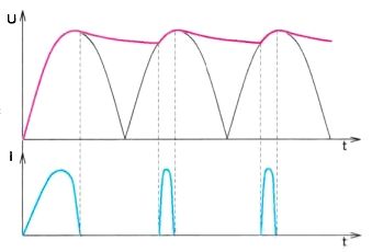
Fig. 2
Most power regulators (brightness) is fazoimpulsnye. Tion key element in them is trinistor (TRIAC), on the control input which at some point to put an opening pulse. For the efforts of this momentum of matter ings economy generally, Neve Lika. To trinistor stayed open through the DOL wives leak certain current, called current feel good hold. In the case of a filament lamp soldering iron or other heater current flows through them all the time, while trinistor is enabled. When the current becomes small when the line voltage to zero, trinistor door. For its opening next poluleriod mains voltage is required once the impulse from the control node. Changing the time of appearance of momentum relative to the start of each half period voltage, you can change the average voltage at the load. As a result, regulated brightness of incandescent (or optimum soldering iron).
If such a regulator "— CFL, the situation changed. The fact is that CFL consumes current when the voltage exceeds sglazhivajushhem voltage condenser BALLASTS. If the spin box opening them pulse enters the trinistor at the time when that condition is not met, it will not open, since there are no conditions for current flow. That is why fazoimpulsnye brightness regulators work with CFL unstable or not working at all.
Although the CFL is significantly more economical than incandescent bulbs, but sometimes you want to Dim her candle. As noted above, widely spread messaging ry reguljato trinistornye races of brightness as a stand-alone and built-in advanced in light fixtures, it is not recommended to apply in conjunction with the CFL. Therefore, for the latter will require specialized dedicated regulator, moreover, a significant consolidation of CFL, working with such a regulator. But there are doubts, is it possible to adjust the brightness of the regular CFL? The answer to this question utverditel th. Only adjust the brightness you can change current through gazorazrjadnuju tube or duration of impulses. After the appearance of the discharge CFL begins to shine, its brightness depends on the current flowing through the bulb the voltage on it changes in a relatively small range. Since some of the pressure falls on Al ment BALLASTS, changing the supply voltage of the CFL, you can change the current through the tube is gazorazrjadnuju, i.e. the brightness of its light. There is conflicting information about how to affect the lifetime of the CFL voltage reduction.
Article v. Cherepanova, a. Korotaeva (Jenergosovet, 2011, no. 3 (16), pp. 65-68) “Исследование характеристик компактных люминесцентных ламп” provides research equipment dependence of illuminance of the working place of the supply voltage for the PEC varying moshhnos and different manufacturers. These dependencies are shown in the Fig. 3. Of them should be that the CFL have brightness adjustment interval is much higher than that of men lights nakaliva, since it is limited from below the voltage at which a CFL no longer work. Yet regulation is quite possible, although to a lesser extent than incandescent lamps. When this interval adjustment pain she got more powerful CFL.
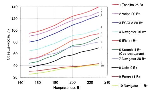
Fig. 3
Since CFL thyristor guljatory not quite Re fit, should make the regulator with kommuti's field element cadaver Tomb, which store is closed when the CE tevoe voltage exceeds some threshold value. The principle of operation of such regulator explained Figure. 4. At the beginning of each half period voltage is supplied to the load. When the voltage exceeds the UERPzistor, Tran closed and the load will be disconnected from the mains. It will open again when the supply voltage drops below UERP. In this case, when you decrease the load voltage, the maximum current consumption does not coincide with maximum voltage. If you change the mains voltage from U1, до U2 will change only the time off and the switching FET and the maximum voltage at the load will remain unchanged For the load, comprising a rectifier with a smoothing filter (like CFLs), this means that the supply voltage will be stable, and this may be an important factor.
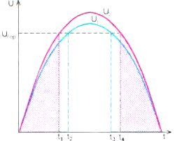
Fig. 4
Diagram of one embodiment of such a regulator is shown in Figure. 5. To simplify it, the supply voltage is rectified beforehand. For the CFL, incandescent lamps or heat protection devices is not crucial. Mains voltage diode bridge rectifies VD1-VD4, On elements of R1, C2 and assembled a hundred parametric VD5 bilizator voltage to power OP AMPS DA1, which assembled kompar Tor strain. Positive about the relationship provides a resistor R8 and hysteresis specifies the resistor R5. At the non-inverting input OP AMPS post paet constant voltage with re zistivnogo R2R3 divider. Sator capacitors C3 further smoothes the pulsation. On the inverting OP-AMP input voltage pulsating with proposal comes the release of resistive Delhi Director R4R6R7, connected to backfeed protection. Variables in d zistorom R6 set threshold voltage. VD6 diode protects the entrance of unacceptably high in emissions exceeding the power prjazhenno OP AMPS. Electronic key on collected by field PTO transistor VT1. Litron stabilized VD7 defends his zat thief surge. On elements C1 and L1 assembled on mehopodavljajushhij LC filter. VD8 diode eliminates the impact of CFL on the regulator if it before pomehopo davljajushhij installed rectifier LC filter.

Fig. 5
When the mains voltage is less traumatizing, invertirujushhem input OP AMPS DA1 voltage is less than vertirujushhem, so the nein on output OP AMPS voltage close to its supply voltage. Field-effect transistor is open, the voltage is supplied to the load If the CFL is connected, sglazhi ing capacitor at the output of the rectifier it (C1 in Fig. 1) is charged to a voltage UERP. The job of the regulator in this case explained Fig. 6. If the threshold voltage UP1 will more amplitude voltage field-effect transistor Oka direction all the time open and CFL operates with maximum brightness. Voltage waveform at sglazhivajushhem condenser BALLASTS CFL and its current trebljaemogo for this case are shown in red. If mouth establish a threshold voltage UERP less network control starts to work. So smoothing capacitor in ELECTRONIC CFL will dawn huddle only to this voltage, which means that the brightness of the glow it will consume less. Shape of voltage and current for this case is shown in blue. Variable resistor R6, you can change the supply voltage of the CFL and its brightness.
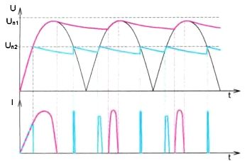
Fig. 6
It should again be noted that in this case, even if the voltage changes, the CFL will post five pulsating voltage with the same maximum value, i.e. the regular supply voltage stabilization will provide provisions on the workload and the brightness of the lamp.
If you compare the shape of voltage and current thresholds for different stresses, it can be seen that when the regulator will begin to reduce the voltage on load, frequency of impulses is getting twice as much, and their duration is reduced because during od leg bottom current through the CFL offers tested twice. Therefore, operations on an output pulse rectifier BALLASTS CFL grow, and their amplitude will decrease. This will cause that ripple brightness will decrease and become a CFL IU it visible.
Здесь следует немного пояснить, о чём идёт речь. Поскольку автогенератор в ЭПРА КЛЛ работает на частоте несколько десятков килогерц, многие потребители думают, а производители утверждают, что у КЛЛ пульсации яркости практически отсутствуют. Но ведь на выходе выпрямителя КЛЛ есть пульсации выпрямленного напряжения, амплитуда которых зависит от ёмкости сглаживающего конденсатора (С1 на рис. 1) и напрямую влияет на пульсацию яркости. Не совсем добросовестные производители “экономят” на ёмкости этих конденсаторов, именно поэтому пульсации яркости свечения КЛЛ могут быть сравнимы и даже превосходить пульсации яркости лампы накаливания.
As for the efforts of current pulses decreases, increases POPs given the interference. It is for them the pressure value is filter C1L1. Of course, this regular supply and to adjust the brightness of the lamps or heating funnels with hog.
Большинство элементов собранного макета размещены на односторонней печатной плате из стеклотекстолита толщиной 1,5…2 мм, её чертёж показан на Figure. 7. Применены постоянные резисторы С2-23, МЛТ. Р1-4 и импортные, переменный — СП4-1, оксидные конденсаторы — импортные, остальные — пленочные, дроссель — серии RLB0608 или аналогичный индуктивностью 47…220 мкГн, рассчитанный на ток, потребляемый нагрузкой. Светодиод — маломощный любого цвета свечения с диаметром корпуса 3…5 мм. Стабилитроны можно применить любые маломощные на напряжение стабилизации 12…14 В. Замена транзистора IRFBC40 — IRF840. Разъём Х1 — клеммник винтовой с шагом выводов 7,5 мм, рассчитанный для установки в отверстия печатной платы.
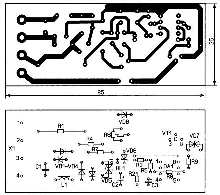
Fig. 7
The appearance of mounted PLA you shown on Figure. 8 (instead of light diode jumper is installed). Her meshhajut in the plastic case, Handl Ka AC resistor shall be of insulating material. The establishment comes down to collection re zistorov R4 and R7 to obtain output adjustment interval also third leg strain.
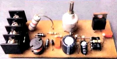
Fig. 8
Diagram of the regulator can be simplified if the threshold element apply logical element on OS Nove Schmitt trigger, for example, Mick roshemu to 561 TL1. Such an element ensuring your quick set-vykljuche ing a key element, but has such a regulator Circuit terezis GIS to Kazan Figure. 9. Anti-interference filter assembled on elements C1, C2 and L1. chip supply voltage stabilizes parametric bilizator stabilitro voltage 100 not VD5 and damping resistor R6, Swe todiod HL1 indicates presence of set voltage first. Protective diodes at the input (output 2) DD element 1.1, since protection circuit built into the chip, and the input current is limited by resistors R2 and R3 Resistor og ranichivaet inrush current when switching on the regulator. Output voltage re gulirujut variable resistor R4.
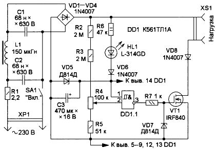
Fig. 9
This control works similarly, but has one feature. The fact of the matter is that due to the large hysteresis trigge RA Schmitt enabling and disabling transistor VT1 occurs at times of personal values of supply voltage. This means that in the first half of each half period voltage amplitude provisions originating network to the load voltage will be greater than the second. It does not matter for heating appliances, but not for the CFL. If the smoothing capacitor in ELECTRONIC CFL will probably not be discharged, the momentum in the second half of the current floor wave voltage may not be. In this case the amplitude of the current increase in the first half, as smoothing capacitor in CFL launch em drained stronger. On the work of the CFL, will not be affected but will reduce the noise generated by the regulator.
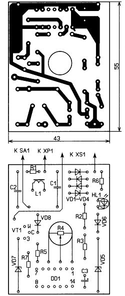
Fig. 10
Simplified fee options, drawing that shows the Figure. 10, is designed for installation in recessed-mounted Luna of transformer power supply (adapter) time measures 50x55x80 mm (without protruding elements) with wall plug. CSS Board tanovlena on cover and axle belt ne resistor goes on the other side. Applied mainly Ana logical parts, to enhance security applied alternating rezis Thor series PC-16S with plastic casing and the axis you can replace IRF840 Transistor transistor IRF710, IRFBC40. Power switch — movement of uniform KBB70-2P2W, but you can apply the thread variable resistor, combined s ' switch designed for operation at mains voltages. Some use boils down to installing output voltage adjustment interval selection of resistors R2, R3. R5.
Free CSS placed side nests XS1. The switch is mounted on the body of the regulator, resistor is installed between the fork and the Board. The appearance of mounted wages shown in Fig. 11.
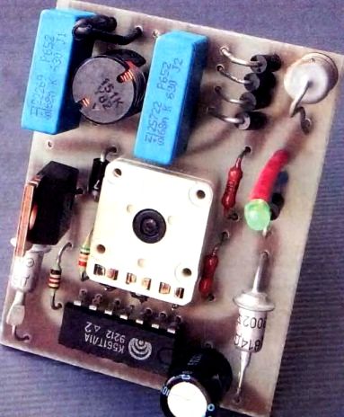
Fig. 11
Even more simplify the regulator can, if we exclude the threshold voltage stabilizer elements. This diagram shows the Governor on Fig. 12. On elements C1. L1. L2 and S2 assembled Interference eliminator, diodes VD1-VD4-bridge rectifier. A diode VD5, resistors R2, R3 and capacitor C3 collected sources power slide chain Nick field-effect transistor VT1. Diode VD5 excludes discharge of the capacitor C3 through circuit regulator and CFL, Zener diode VD6 limits stresses on gate field effect transistor model. Diode VD7 eliminates the impact of CFL on RA bot regulator, if she is at the entrance (to the rectifier) stood in the direct pomehopodav mouth LC filter.
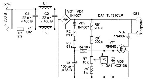
Fig. 12
As porogo first device when used parallel chip lizatora stabilized voltage series TL431 (DA1). Its peculiarity lies in the fact that when the situation present control voltage input (1) less than 2.5 in the current through it exceeds 0.3-0.4 Ma when the voltage exceeds the specified value, the current through the mikroshe Mu dramatically increase.
At the beginning of each half period set at the control input voltage recovered chip DA1 voltage-IU it 2.5 in, talk through chip DA1 small, so voltage condenser RA C3 enters the breech open transistor VT1. In this case, the voltage is supplied to the CFL. If no resistor engine prjazhenie Pres vysit 2.5 in (which corresponds to, for example, the voltage UP1 на рис 6), полевой транзистор будет всегда открыт (напряжение затвор—исток – 13 В) и на нагрузку поступает всё сетевое напряжение. Когда напряжение на движке резистора R7 превысит 2,5 В (например, если установлено UP2), the current through the chip will increase, and the voltage on Gate Transistor decreases to 2 result in field-effect transistor closes and the load will do the voltage UP2 for only part of the bottom of the network Because the voltage on gate field-effect transistor limited stabilitronom VD6 and current through the rezis Tor R4 limited resistors R2 and R3, the voltage on the capacitor C3 not Pres vysit 25 ... 30 in.
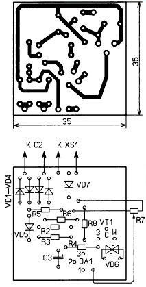
Fig. 13
Compared to the previous design of the whole controller was able to place in a smaller case (40x42x57 mm). Therefore, the elements are placed on two boards, the main Drawing is shown in Fig. 13, and additional that has a filter on Fig. 14.

Fig. 14
Boards glued inside (fig. 15), on its walls have mouth switch SA1, variable resistor R7 and HS1. Resistor R1 is set on the findings of the switch and plug and HS1 Fig. 15 is not visible. All with Unity held wire MGTF.
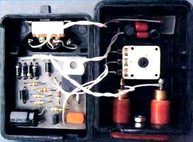
Fig. 15
The device applied basically the same elements as in previous designs. As the regulator of PLA nirovalos used in conjunction with the CFL were applied less powerful chokes (from CFL BALLASTS). The appearance of the regulator is shown in Fig. 16.
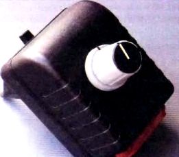
Fig. 16
Fig. 16
По сравнению с тринисторными регуляторами яркости, где частота импульсов тока через нагрузку — 100 Гц. В предлагаемых она может быть вдвое больше. Поэтому и пульсации яркости меньше. Кроме того, если с помощью регулятора напряжение на нагрузке уменьшено, максимум тока не совпадает с максимумом напряжения. В этом случае “верхушка синусиоды” не будет “срезана” и её форма в сети должна улучшиться.
This regulator can be applied with any low-active load. Lower limit adjustable power on it depends on leakage current of closed field-effect transistor.
Author: I. NECHAEV, Moscow
Source: Radio No. 4/2017