Naviny.by offered device can enable and disable the load with the touch of a finger on a touch-sensitive contact: when lane PTO touch lamp is switched on, the next is extinguished. Load mouth device can be an incandescent lamp with power up to 100 Watts. jenergosberegaju liquid compact fluorescent (CFL) or led bulb.
Unlike structures, bathrooms published earlier [1, 2], proposed you kljuchatel contains far fewer details — it's all on the Nene meet single chip and network switching voltage situation carried out field-effect transistor with a small resistance resistance to an open channel, thanks to which it was allocated a small output. The disadvantage is the need to include it in the trehpoljusnikom network, but Dan Noah constructions (primenitel but to the tabletop lamp) under Tage is not significant, this one.
Switch scheme led by Dena Fig. 1. Mains voltage via the Insert plavkuju FU1 comes on switching power supply U1 the output constant voltage 5 v and permanent diode th bridge VD1-VD4, Vert Nahl which included channel field-effect transistor VT1, When inclusion NII devices in the network chain S3R5 USTA General counter DD 1.1 and condition zero (all outputs — log 0). At the same time starts to Flash flashing led NL1, Nye prjamougol pulses with its cathode arrive at the accounting entry (9) counter DD 1.2 and change its State. When the signal at the output of the 8 (14) high-level voltage across the diode VD5 arrives at the accounting entry (9) counter and blocking its further work.

Figure. 1
When you touch the ball to the pin board E1 sensor voltage, restore my lighting network on human body ages, arrives at the input R (15) counter DD 1.2 and sets it to zero State. The downward spiral (capacitor C4 discharged) at the entrance permission account (2) DD counter 1.1 changes its State. High-level voltage with its 3 output through resistor R3 arrives at shutter field VT 1 zistora Tran and opens it, Tata in which voltage situation comes EL1 Pampa with rains network. Duration Sep touch Sora E1, as well as repeated prikosno prior to stopping account account Chica 001.2 do not affect the State of the counter (DD) 1.1.
Для того чтобы отключить лампу ЕL1, нужно снова прикоснуться к сенсорному контакту Е1. Счётчик DD1.1 вновь изменит своё состояние на единицу, на выводе 3 появится напряжение низкого уровня, и транзистор VТ1 закроется. Время “нечувствительности” устройства после прикосновения к сенсору (t) зависит от частоты вспышек f светодиода НL1 и коэффициента деления счётчика DD1.2. Для уменьшения этого времени правый (по схеме) вывод диода VD5 (анод) и конденсатора С4 можно соединить не с выходом 8 (вывод 14). а с выходом 4 (вывод 13) или 2 (вывод 12) счетчика DD1.2 (в первом случае время сократится вдвое, во втором — вчетверо).
U1 power supply-charger HX 128-5 for mobile phone with an output on permanent tension in 5. you can use any suitable goto St or homemade low-power switching power supply with output voltage of 5th ... 6 in and shock load 30 Ma. Selection criteria — efficiency and minimum heat elements with long-term continuously ensuring uninterrupted operation.
All used in device con densatory — ceramic, e.g. KM, all resistors-MLT as indicated on the diagram of power dissipation, Resistor R1 is used for protection against electric shock when Sri prikosnove to touch contact E1. Electrical breakdown maintenance in order to his Corps allowed value the permanent and alternating voltage of the resistor should be not less than 500 b. this requirement to meet the specified type resistors with powerfully Stu 1 Watt dissipation and above.
Диоды 1N4007 (VD1—VD4) заменимы любыми другими кремниевыми с прямым током не менее 0,5 А и обратным напряжением не менее 600 В или диодным мостом с такими же параметрами. диод КД522А (VD5) — любым маломощным кремниевым диодом, транзистор VТ1 – любым n-канальным полевым транзистором с максимальным напряжением сток—исток не менее 400 В. Микросхема К561ИЕ10 может быть заменена функциональным аналогом из серии КР1561 или 564, Мигающий светодиод HL1 — красного цвета свечения с частотой вспышек около 1 Гц, тип его автору неизвестен. На его месте можно применить любой мигающий светодиод с минимальным напряжением питания около 2 В.
Design mouth device may be different — it can be embedded into a suitable ready or self-made lamp or you perform as a console, included between the lamp and the network in the English version, the author details the device geared smon two fragments of the layout of the printed board, placed in the enclosure self-made svetil NIKA. One con tinue the holder the fuse link FU1, diode bridge VD1-VD4 and transistor VT1. With the power of incandescent 100 W Tran zistor virtually no heat ditional and therefore heat sink for him. On the second Board are 16-gnjozdnaja socket under the DD1 chip and all the other details. Resistor R1 is cut heat shrinkable tube and mounted hinged mounting inside COR Pusa. U1 power supply Board checked out from the charger, the details of the output of the rectifier (diode castle looks onto an amazing vyprja and oxide Kon densator) moved closer to the center of the Board, then it cut to length. The finished boards are covered on both sides by two layers of varnish ХВ-784.
The design of the car manufactured rum decorative luminaire Che razhena on Figure. 2. Источником света в нём служит “Светодиодная система model YB27” производства КНР, представляющая собой лампу со светодиодами красного, зеленого и синего цветов свечения, снабженную вращающимся колпаком из прозрачного пластика с гранями-призмами Световая картина, наблюдаемая на потолке, напоминает ту, которая создаётся широко известным вращающимся “диско-шаром”.
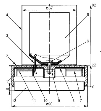
Fig. 2
Основание светильника 1 — дюралюминиевый маховик от катушечного магнитофона. На нём установлен цилиндр 4 (банка из-под зелёного горошка), внутри которого находится керамический патрон 5, закреплённый на основании 1 с помощью винта М4 (6) с гайкой 9. Между цилиндром и основанием помещён алюминиевый диск 2 (от отслужившего свой срок электросчётчика), закрывающий отверстия на верхней плоскости основания 1. Внутри основания установлена изолирующая прокладка 8 (полиэтиленовая крышка для стеклянной банки), к которой “секундным” клеем приклеены согнутые в виде буквы П полоски плотного картона 10, пропитанного лаком ХВ-784. С помощью клея и тонкой рыболовной лески к ним прикреплены платы 7 и 11 с деталями устройства. Съёмное днище 12 — ещё одна полиэтиленовая крышка, немного обрезанная по высоте и плотно вставленная в основание светильника 1. Наружные поверхности деталей корпуса светильника окрашены матовой чёрной аэрозольной краской. Вид на монтаж деталей в основании светильника показан на Fig. 3, While its appearance is on Fig. 4.
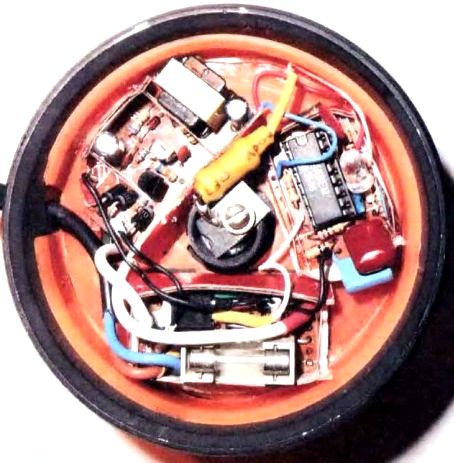
Fig. 3
Смонтированное правильно и из исправных деталей устройство начинает работать сразу; налаживание сводится к установке необходимой чувствительности подбором резистора R2. Для упрощения этой процедуры резистор R2 временно заменяют включённым подстроечным реостатом такого же сопротивления, а между выводом 14 счётчика DD1.2 и плюсовым проводом питания через резистор сопротивлением 1… 1,5 кОм подключают любой светодиод (катодом к указанному выводу), При работе счётчика DD1.2 светодиод должен светить, при остановке счета — гаснуть. Иными словами, по прошествии восьми вспышек светодиода НL1 после подачи питающего напряжения дополнительный светодиод должен погаснуть. Если этого не происходит, уменьшают сопротивление подстроенного резистора приблизительно на 100 кОм. добиваясь погасания дополнительного светодиода. Далее прикосновением пальца к сенсорному контакту Е1 устанавливают счётчик DD1.2 в нулевое состояние, при этом дополнительный светодиод должен засветиться, а после восьми вспышек мигающего вновь погаснуть. Если устройство работает нормально, удаляют временно подключённый светодиод, заменяют подстроечный резистор ПОСТОЯННЫМ близкого сопротивления, ввинчивают лампу ЕL1 в патрон и проверяют работу светильника в целом.
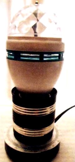
Fig. 4
The resistance of the resistor R2 2
When establishing la switches should remember that its elements are galvanically connected with the network of cops, so while some of Bani must be taken, and all work is done only when fully obesto connected device. Shown in the diagram, the common wire should never be associated with Corpo com device; light with metal housing allowed repents exploit exclusively dedicated to the premises, have insulating floors Seaway MRA teriala. far from conduit Dov, radiators and other metal grounded tional items. Exploitation of this fixture in damp and wet areas is unacceptable.
LITERATURE
- Erofeev B. Economical touch switch illumination Radio, 2001, No. 10, 29. 30.
- Cherevan O Touch switch table lamp. Radio, 2003, No. I. S. 16.
Author: A. MELNIKOV, Barnaul
Source: Radio No. 4/2017