Автор предлагает оснастить светодиодную лампу таймером, through a fixed time span it disconnect means.
В статье автора “Регулируемая сетевая светодиодная лампа” (“Радио”, 2017, № 5, с. 27, 28) были описаны варианты оснащения светодиодных ламп, собранных на микросхемных электрон ных драйверах, регуляторами яркости (как плавными, так и ступенчатыми). Такие лампы весьма несложно дополнить таймером, описание которого приведено далее. Он выключит лампу через определённый временной интервал после подачи на неё питающего напряжения. Для последующего включения лампы необходимо кратковременно (на 1…2 с) отключить питающее напряжение и затем вновь подать его. Сделать это можно с помощью штатного выключателя освещения.

Figure. 1
Timer circuit and connect it to the driver led lamp trade brand chip Camelion howling BP2832A shown on Figure. 1. Нумерация штатных элементов лампы приведена в соответствии с маркировкой на её плате, а вновь введённых, которые выделены красным цветом, — продолжена. Но сначала следует сказать о способе выключения драйвера. Значительная их часть в светодиодных лампах собрана на специализированных микросхемах, “начинка” которых питается непосредственно от сетевого выпрямителя. Для этого в состав таких микросхем входит стабилизатор напряжения с встроенными или внешними гасящими резисторами. Для сглаживания пульсаций этого стабилизатора используется внешний конденсатор (очень часто керамический) относительно небольшой ёмкости. Для его подключения у микросхем имеется специальный вывод.
When closing this finding with the overall conclusion some chips power that its sites will be de-energized and the driver stop working-lamp will go out.
The timer itself is assembled on the field output transistor VT1 and VT2 Schmitt trigger schema with vremjazadajushhej RC-circuit C6, R10. Drain transistor VT2 is connected to the condenser filter chip power C4 U1. When the transistor is opened power chip nodes NIE tension decrease decreasing fractional volts, and it suspended its work laid down. Selection of impulse output Tori 2N7002 due to their very highest you limit parameters: voltage bolt — source is ± 40 in drain voltage-source-60 in.
После подачи питающего напряжения на таймер поступает напряжение 20…23 В с резистивного делителя R7— R9. Конденсатор С5 сглаживает пульсации выпрямленного напряжения и подавляет помехи от драйвера. Начинается зарядка конденсатора С6 через резистор R10. Транзистор VT1 open and VT2- закрыт, поэтому драйвер светодиодной лампы работает в штатном режиме. По мере зарядки конденсатора С6 напряжение на резисторе R10 уменьшается, и когда оно станет меньше 3…4 В, транзистор VТ1 начнёт закрываться и напряжение на его стоке станет расти. Это приведёт к открыванию транзистора VТ2, and then comes the moment when they abruptly switch Xia-VT1 VT2 closes and opens. Supply voltage will decrease to about chip nodes 2, results of Tata. lamp
RC time constant circuits C6, R10 for the specified denominations diagram τ = C6 · R10 = 15 · 10-6·3·106 = 45 s. like this and should be delayed, you are correct. But it should be remembered that, by definition, the time constant is the time interval during which a capacitor charged to level 0.632-UPit (UPit — напряжение питания RС-цепи). В данном случае конденсатор С6 заряжается примерно до (0,8…0,9)·UPitTherefore, the delay turns out to be approximately twice as much. The experiment showed that the time delay switch-off bedroom-1 min 25 sec. Of course, the stability of time delay is low, but this is not the proposed design has significant leg values.
In this mode, the lamp can prop-hurr indefinitely, while the current consumed from network talk significantly less than full-time. Measurements with lamp Camelion showed that current consumption-35 Ma reverse position and 8 MA in the off.
Чтобы вновь включить лампу и запустить таймер, необходимо отключить сетевое напряжение на 1…2 с. За это время конденсатор С6 успеет разрядиться через диод VD1 и резистор R9. После этого подача сетевого напряжения включит лампу, и отсчёт времени начнётся заново.

Fig. 2
Timer on a one-sided PCB, its drawing is shown in Figure. 2, and the location element Fig. 3. To reduce the size of the fee applied timer elements for surface mounting. Capacitors, tantalum-satory-1206 size resistors. Short segment MI insulated conductors charge Tai measure connected with the driver Board lights. After checking the operational productivity charge timer paste to her heat-resistant glue.
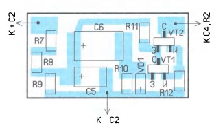
Fig. 3
If the lamp housing allows you to use the hatchers details, you can apply the 2N7000 datasheet transistors, rezis Torah-MLT, r 1-4, 2-23, diode, 1N4007-capacitor C5 can be any, and C6 preferably apply tantalum, leakage current less than him. You can not change Board topology, only the conclusions elements make the holes in the Board.
Shutdown delay time you can change the selection of elements of C6 and R10. Increase their denominations actuators dit to increase delay time. But we should not forget about the leakage current of the capacitor, which usually grows with the increase of its capacity, and the reverse current diode. Therefore, accompanied with the Nations of the resistor R10 must be not more than 10 MΩ.
This timer has been set and the led bulb Available brand with capacity of 7 Watts. In her application of NENA JW1779 chip. Dry this faith scheme lamps and the timer connection shown on Figure. 4. The elk that when closing capacitor C3 lamp turns off not fully, LEDs continue to shine with Su mainly lower intensity. This effect can be used to prepare Nations security lighting. After the first cycle the timer lamp goes into standby and shines weakly after switching off and follow the future inclusion of it begins to shine with nominal luminance and aging time again goes into standby mode. Consumed Lam sing current at nominal brightness — 27 Ma and in standby mode it reduces decreasing to 7 Ma.

Fig. 4
Для управления этим драйвером сопротивление резистора R12 не должно превышать 2…2,5 кОм. При большем сопротивлении драйвер остаётся включённым. Но и это ещё не всё. Оказалось, что при сопротивлении резистора R12 в несколько сотен ом переход в дежурный режим сопровождается серией из нескольких вспышек. Обусловлено это следующими причинами. Во-первых, от сопротивления резистора R12 зависят порог переключения и гистерезис триггера Шмитта. Во-вторых, на резисторе-предохранителе FU падает часть сетевого напряжения. После переключения триггера лампа переходит в дежурный режим и потребляемый ток уменьшается. Поэтому напряжение на выходе выпрямителя увеличивается, триггер переключается в первоначальное состояние и лампа включается. Затем триггер вновь переключится — лампа перейдёт в дежурный режим. Так пройдёт несколько циклов (несколько вспышек), и в итоге лампа окончательно перейдёт в дежурный режим. Этот эффект можно использовать для сигнализации окончания времени выдержки.
Similarly, the light was finalized led lamp Available brand power 10 W. This lamp driver circuit corresponds to the figure. 4, except that the meaning of the applied mikroshe Ma BP9912C, capacitance capacitor C2 is 2.2 µF, the resistance of the protective resistor-fuse is marked with leg as FU-200 Ohm and R2 - 100 kohm. In nominal consumption mode that lamp current-36 Ma, dezhur mode-7 Ma.
Author: I. NECHAEV, Moscow
Source: Радио №6/2017