It is known that to regulate the voltage at various experiments required laboratory auto transformer. However, if it is not, You can use the transformer as described in [1]. To improve the speed and convenience of working with such a transformer in our time has been developed and is described in [2] control unit. Unfortunately, it is quite complicated, because is built on logical mikroshe Max low and medium degree of integration. The author offers Ana logical control unit on the microcontroller.
The principle of operation of the block remained the same — to each of the possible values of output voltage line welcomed the binary code, commute ate appropriately secondary obmot Ki transformer. In the same way as in proto type, unit does not measure output at prjazhenie, but only shows the RAS an even value. Thanks to mikrokont rolleru have been able to significantly reduce the number of stitching details in block, dramatically simplifying design and manufacture ing circuit board, and also include ing device.
On Figure. 1 the scheme of control unit based on micro controller PIC16F628A-1/P (DD1) and storage register SCREEN IR22 1554 (DD2). You could implement it at a cheap microcontroller PIC12F629 and two shear registers-serial code converters in parallel. But such a device would succeed less resistant impulse noise, always bezhnyh when switching with high inductance relay electromagnetic Elec and windings of the transformer.

Figure. 1
For dynamic nodes display the interference is not dangerous because the indicator is constantly being updated, and the disturbance would lead, in the worst case, to briefly show distortion. However distorted code filed on the keys that control switching relay, transformer winding specialist can lead to unexpected filing of dangerous load for her raised leg strain. Therefore, the selected number of conclusions rokontroller Mick enough for direct formation of parallel code on them control relay.
Since CE microcontrollers Nigeria PIC16F628 internal resistors connecting inputs plus sources Nick supply, installed only on the lines in the port, resistors R1-R4 perform the same function on the lines of port a. VT1 Transistors — VT3 communication tirujut common anodes bits of light diode indicator H01. The dosing impulse output keys, commuting using using relay secondary winding TRANS formatora, control signals on output storage register tread DD2.
After power program the microcontroller writes zero howl code in one of its internal registers and register DD2. This is to ensure that the transformer is always begin with a zero tension at output that will protect from accidental damage to him podkljuchjonnuju low-voltage load.
Next, the program transfers the register output mode DD2 recorded code into it by adding it to the entrance of ED low level. Register output binary code voltage arrives at the cadaver Tomb stornye keys, control relays, switching the windings of transformer power transforme. These keys are similar to the obve djonnym shtrihpunktirnymi lines on the diagram shown in Figure 1. 2 in [2]. Outputs connection address register DD2 reporting devices are marked in accordance with the same schema.
The program then converts the voltage code realistic Feb semijelement tional codes digits three digits led HG1, stubbing while trailing zeros. She alternately displays these codes in the port, including simultaneous desired level indicator installation of the lines RA0, RA1 or RA7. Output cycle three digits takes about 360 Ms. Such a length indication cycle activities, and depends on the speed of change tension on the output transformer, chosen on purpose. On the one hand, the output voltage of the transformer is changing quickly enough and melt but, on the other hand, the time intervals between electromagnet tional relays are sufficient for the completion of the transition processes in the Torah that inch transform reduces arcing contact Tov relays.
At the end of each cycle of indie program checks the State of the buttons SB1-SB4 and if none of them pressed again writes the binary number from the register of memory mikrokont roller in register DD2, and then about the process is repeated. This is the main mode of operation in which the device finds Xia until you clicked any of the buttons SB1-SB4.
When you click the SB2 and its binary retention voltage increases by one with each cycle, which corresponds to an increase in the voltage at one Volt. If the button is pressed, press the button and SB2 SB3, tension will rise in increments of 10 until reaching Mack simuma (255) further increase the voltage stops regardless of the State of the buttons.
Note that if SB3 is pressed voltage rise may end sooner than would be tignuto 255 in value of DOS is that attempting to add 10 to the number exceeding 245 shajushhemu result perepolne NIJ vosmirazrjadnogo register and setting the the output transformer to the emissions in the range from 0 to 9 in. such actions programmatically disallowed. Voltage can be achieved to maximize, leaving only SB2 button pressed.
Similarly, a button and a button for running the SB1 SB2, but it reduces the tension. If you accidentally press the buttons SB1 and SB2 simultaneously, priority will be given to the button SB1, and output voltage of the transformer will be reduced.
When you need to install the required voltage without draining vain resource relay on numerous switching, you can register online using quick mode installation. To enter click the SBZ and uder her zhivajte until the decimal point will be included in the low discharge control RA HG1.
In this mode, the duration of the display cycle reduces surrounding Ness approx. 200 MS and voltage on the gar de transformer remains unchanged and is not dependent on the meter until the control unit will not be returned to native mode. The buttons SB1-SB3 indicator should be set to the desired voltage as described above, and then click or hold, if it has been pressed, press the SB3, until the device will return to native mode and will not be installed again specified voltage .
If you want to return to the main mode, not taking a new value, you must hold down the button SB4. The same will happen if, within a period of approximately 5 is pressed with no buttons. In native mode, the button is used for output shutdown SB4 stresses. Clicking on it will install Lena zero value on the indicator and the zero voltage on output TRANS formatora.
Because buttons status polling occurs at the end of each cycle, the device responds to pressing buttons is not instantaneous, and for no more than one cycle, supplemented with Indica. For this reason, you must hold the button pressed until the meter change.
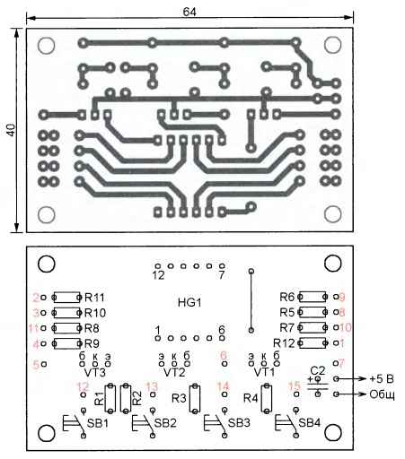
Fig. 2
The device is mounted on two printed circuit boards, as shown in Figure. 2 and Figure. 3. This option proved to be easier than distributing printed wire the same Board. Boards designed on the installation of permanent power resistor imports 0.05 Watts. Accompanied with the Nations of resistors R5-R12 can be between 330 Ohms to 3.3 k ohms depending on the brightness of the indicator and its type. Capacitors C3 and C4 are soldered directly to the power supply. Chip SCREEN 1554 IR22 can be replaced with 74AC373N or 74HC373N.

Fig. 3
Board mechanically connected between a the parties printed wire nicknames inside using four pain 10 mm height uprights and pulse. To the body block this Assembly attached CZK shtejnami of galvanized steel Tol anniversary 0.6 mm. On the photograph Figure. 4 shows the appearance of the control unit without housing. Pads of both boards with the same numbers red connected isolated KET wires. A similar application in njonnomu [2] electronic keys node can be assembled on the printed circuit board, shown in [2] in Figure 1. 4.
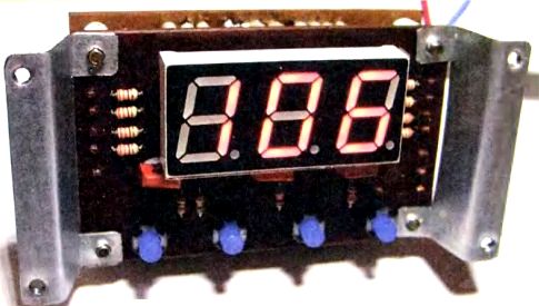
Fig. 4
Power management unit being described ing provides a separate network transformer with output tension is dissipated in 10 and not less than 5 in. This option is preferable to Pete from further winding basics leg transformer. The fact of the matter is that when the closing price in load tests leg transformer, it is quite likely in practice, poorer mental radio, voltage at his secondary windings, including supply management, node falls. This can cause the very arbitrary switching relays, and even zapping their contacts. When Pete Sri from a separate transformer, such problems do not arise. Moreover, smaller pickups on the microcontroller from power circuits.
Power supply node is assembled according to the scheme, shown on Figure. 5. Нумерация элементов на ней продолжает начатую на рис. 1. По цепи +12 В этот узел должен обеспечивать ток, больший суммарного, протекающего через обмотки всех реле, в 1,2…1,5 раза.

Fig. 5
+12 voltage at the relay winding arrives at K1-K8 [2] not immediately after filing the transformer T1 line voltage, but only after clicking on the SB5 and triggering additional suspicious relay K1. Until then all relays de-energized winding, so Mu output voltage laboratory Guo transformer remains zero regardless of the status of the control unit. Otherwise random code in the register which spontaneously DD2 at the time of filing of Pete and continued up to the first record in it the correct code mikrokontrol lerom would cause short contact only in translation output TRANS formatora arbitrary stresses, even maximum. Press the button only appears after the SB5 ing scratch on the indicator HG1.
Board power node IP polzovana ready from power sources power antenna Wuxi litelja nickname. Relay K1-RAS-1215 winding 400 Ohm resistance, similar to the application of njonnym in [2].
Mikrokont roller program written in MPLAB IDE v Wednesday 8.92 MPASM assembler language. For receipt of semijelementnyh to Dov digits used pro gram, described in [3]. With proper installation of NALA device does not establish Tre take and starts to work immediately.
LITERATURE
- Terskov V. in increments of one volt. Radio, 1993, N° 9, pp. 24, 25.
- Gerasimov E. the control Unit of the laboratory transformer. Radio, 2016, no. 9, pp. 27-29.
- Kozhukhin P. Program — reference codes for output indicators. Radio, 2010, № 6, p. 34..
Download the file to the project
Author: GERASIMOV, a village of Vyselki of Krasnodar territory
Source: Радио №6/2017