Now widely used about handsets powered by a three-phase network, requiring compliance with the order of phase sequence. This is typically achieved the appropriate COM mutation wires.
Often, however, a number of renovations, Kog Yes used additional feeding cable or temporary enclosures, while often switching on phase order violation occurs, which can cause you hoard of equipment failure. The proposed indie cator phase sequence allows you to quickly determine pour violation phase sequence if it is.
Work device
Scheme indicator is shown on Fig.1. Work em indicator as follows. The voltage between any two phases that must follow one after the other (a and b, and c and a) through Nye limiter resistors R1-R4 comes on Here and us stabilitro voltage stabilization VD2 12 in. Thus, on these stabilitronah get Xia impulses positive tension about the 12 tudoj ampli. These impulses voltage Che Rez diodes VD3 VD4 and charge a capacitor C1, which is used to supply power to the indicator.
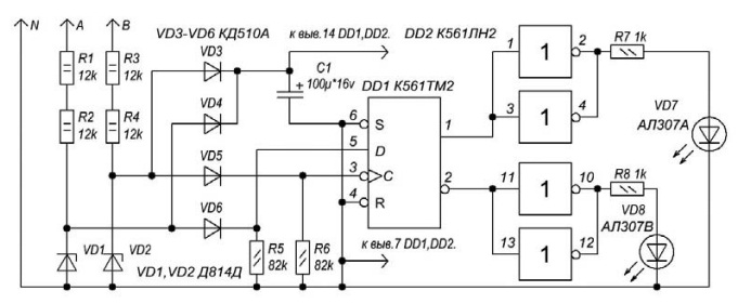
Figure. 1
Through the diodes VD5 VD6 and positive pulses to them (the width of these pulses is almost equal to the duration of half period voltage network) arrive:
- from phase and at the information sign D;
- in phase at the clock input to trigger DD1.
Сигнал с информационного входа триггера передается на выход триггера по фронту тактового импульса. Учитывая сдвиг фаз на 120°, это приведет к тому, что в случае правильного чередования фаз на прямом выходе триггера DD1 будет присутствовать высокий уровень, а на инверсном вы ходе – низкий уровень. Эти уровни напряжения после инверсии логическими элементами DD2 заставляют светиться зеленый светодиод VD8.
В случае неправильного чередования фаз, на прямом выходе триггера DD1 присутствует низкий уровень, а на инверсном – высокий уровень, что приведет к свечению красного светодиода VD7.
Diagrams explaining the operation of the device, shown in Fig. 2.
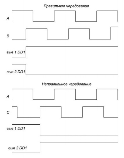
Fig. 2
Unused IC inputs in the schema and need to connect DD2 DD1 to common wire device.
Author: Vyacheslav Kalashnik, Voronezh
Source: Radioamator No. 4/2017