Are often the amateur 3-way chat sound much worse than their industrial "collect EV due to the fact that all heads of the AU are in the same plane. The fact of the matter is that in the same plane should not be fixing the place of heads, and their acoustic centres. 100 article describes how to do this.
For the correct playback of meandering, the first approximation to a real musical Mo the signal to which the sine wave has nothing at all, should be PRA Villa phase of all its constituents, or at least the first harmonic 5-6.
The acoustic centers of the treble, MIDRANGE and bass heads the majority of 3-band AU do not coincide, since they are in the same head TPS skosti.
So if the acoustic Center tweeter will be located closer to the listener, its akustiches kya swings come in listening point earlier than it should be, and the signal frequency 1 kHz meander will be distorted, as shown in the Fig.1.
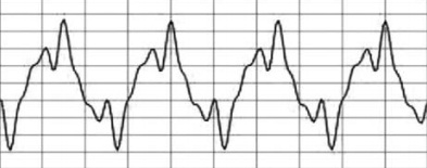
Figure. 1
Only when the correct spectral phase with providing it will print meander meander (close to his form), as shown in the Fig. 2.
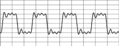
Fig. 2
Thus, for the correct playback of Denia acoustic signal 3-way speaker is not required post outlets within its structure acoustic heads for the depth of the speaker cabinet. In order to do it right before the proposed use this simple device.
Work device
At the entrance of the proposed devices (fig. 3) You can serve as a signal from laboratory GE neratora sinusoidal signals and au DIO card computer, once the signal in computer audioeditor.
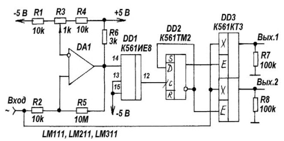
Fig. 3
Trimpot R3 on invertiru Ed comparator output DA1 exhibited Ta some voltage to the voltage at the output of the comparator side of -5 level in the level of +5 in on going sinusoi dalnogo input signal through zero.
In EAMES DD1 (fig. 3) executed divider h toty pulses with the release of the 10 DA1. Conclusions of the R and S IC connected to -5 in DD2. This use of ICS used in trigger mode across the input h Tautou on 2. Signal outputs trigger DD2 pooche redno includes upper or lower on diagram key switch ICS DD3. As a result "Output. 1 "and" Out. 2 "will alternately receive packs of 10 periods of the sine wave with frequency input leg signal.
Considered the scheme also allows to give to "Output. 1 "and" Out. 2 "packs containing from 2 to 10 sine wave periods in each. To do this, the signal from the corresponding counter-divider output file for DD1 DD entry 2.1 and hook up to the entrance of the dumping DD1 (pole. 15).
This device to power all the EAMES used supply voltage ± 5 v, which provides the output signal span kompa Rathor from +5 in to -5 in.
Comparer you can use any op DA1 high-speed operational amplifier which operates at supply voltage ± 5 in.
Working with device
Acoustic heads the AU must first be held to a microphone without connecting the crossover. If the acoustic centers on display correctly, then move the measuring microphone farther/closer to the AU should not lead to from on the ratio of phases.
Signals with "closed. 1 "and" Out. 2 "served on the BASS and MIDRANGE, and then at the midrange and tweeter speakers. Configuration is done using OS dvuhkanapnogo cillografa, in which the signal from the measuring th microphone onto screen at Whitefish NAL from the generator.
If on the oscilloscope screen has an absence without a single period or a bundle of PE riodov on top of each other, this means that the signal from the AU head lag for the period. If the acoustic centers all heads are combined properly, nor the absence of part of the signal, nor his overdub. When working with rojstvom lessening possible mouth amplitude lane closed in sinusoids bundle, especially BASS head.
It is advisable to make such measurements, if possible, by sending the AU from a covered window, i.e. using the playback mode of the open space.
Incorrect playback signal th lovkami 3-way AU demonstrates the Fig. 4, and, а правильное – на Figure 4, b.

Fig. 4
Of course, you can place acoustic th skill in one plane and use several Ku signal fed to them. On Fig. 5 show but how can I change the FChH and chart the direction of the AU using the delay signal. On Fig. 5, and dashed line shows the scope in which the rays 2-lane AU will phase without taking special measures. On Fig. 5 b so far, said the change in the scope in which the bass and treble heads radiate in phase with the IP using the delay signal applied to the BASS head. Ta Kim way delay LF whitefish NALA considerably improves sound quality Ka and her chart changes direction.
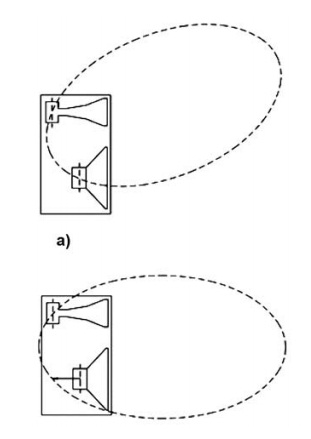
Fig. 5
However, the band sound Cha it implement delay whitefish NALA analog way without distortion, very difficult context. Therefore produces Xia combining acoustic centres in the vertical plane, more often than not, just making the front panel AU slant.
Fazolinejnye crossovers
To 3-way AU Pré correctly formed an electrical signal in the sky connection is not enough to combine the acoustic portion of its prices it is necessary to use more heads in it that do not make crossovers, phase iskazhe. And here the field for manoeuvre. Passive crossovers, but the first to row, due to significant phase shifts, use the undesirable. And crossovers for 1 row does not give the desired damping out bandwidth, thereby not provide you Noe separation frequency bands submitted at times personal AC.1 head
Для того чтобы обеспечить одинаковое групповое время задержки (ГВЗ) акустического сигнала (это надо для правильной передачи его формы) надо уменьшить задержку НЧ составляющих в нём. А вот ГВЗ как раз и зависит от порядка пассивного фильтра. Поэтому в 3-полосных АС, в качестве пассивного фильтра для ВЧ головки используют фильтр третьего порядка, для СЧ-головки – второго, а для НЧ-головки – первого порядка (это может быть просто индуктивность).
But such a decision creates the risk that ing Sarn BASS filter with low slope provides a fairly large frequency range, where LF and MF are working together, which is not very good.
Таким образом, в настоящее время, наиболее популярные решения – это использование активных и цифровых кроссоверов. Особенно популярны, для построения фазолинейных систем, цифровые фильтры с конечной импульсной характеристикой (англ. – FIR).
Conclusion
You will often come across the assertion that "correct" sound is determined only by the special ktrom signal, and, they say, phase correlation between his constituents is not important. It is fundamentally not true.
As shown above, in order to pass even Vilna PRA easy signal as meander, it is necessary to properly convey not only level all of its harmonics, but also their phase.
It is FChH AU defines the relationship between a personal once frequencies present in the signal, requirement to eliminate relative to each other. Thus, timbre and characteristics that would produce the listener identify one or another instrument or sound document depends not only on its spectral devices under the whole, but as part of the harmonic spectrum relate to each other in time.
Prepared by: Andrey Semenov, Vladivostok, Russia
Source: Radioamator No. 4/2017