This article discusses the different types of drivers from the company Texas Instruments (TI) to control the main types of DC motors. This article also discusses the design features and DC motor control algorithms.
Электродвигатель, как тип электромеханического привода, используется очень широко, буквально во всех сферах жизни современного общества В офисной и домашней технике, в системах мониторинга и управления зданий и объектов повсеместно используются электродвигатели. которые являются одной из основных составляющих любого производства. Электромобили и роботы – вот сферы применения где электродвигателям уготовано впечатляющее будущее.
Technology development has resulted in traditional engines have improved and all new applications. Robotics and with temporary precision machines and vaporizer are unthinkable without engines with intelligent control systems.
Different types of electric motors and their features.
The first electric motor, electrical converter coy energy in rotational movement, was created by scientists in Jacobi skim Eng 1834 year. It was later Xie rezno improved and many new options, but you used when you created the principles of electromagnetism are still the basis of all DoD difikacij modern electric motors.
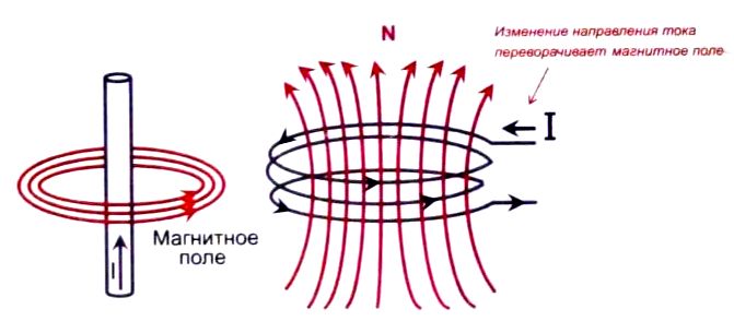
Figure. 1
As you know, the conductor with passing on it current (fig. 1) creates around itself, the intensity of the magnetic field (magnetic induction) which is proportional to the number of revolutions, in the case of coil (m) and the largest about walking in her current (I):
IN = K • N • (I),
Where is:
I – сипа тока;
В – вектор магнитной индукции;
N – число витков;
К – магнитная постоянная.
When changing the direction of current flow changes the direction of the magnetic field and the conductor. On premises in whelping external magnetic field guide with shock dei welcomed the Lorentz force, causing its rotational re recovery.
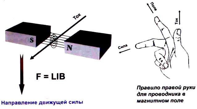
Fig. 2
To determine the direction of rotation is used right hand rule for a conductor in a magnetic field (fig. 2). In this case, the force (F), acting on a conductor in a magnetic field, equal to the length of the conductor (L) added to current (I) in a conductor the magnetic induction field (B), i.e. P = I. • I • V.
Commutator motors
Commutator DC motors (for their presence ensuring company T1 uses the acronym BDC) are widespread. This engine contains 100 Tor. consisting of permanent magnets, magnetic pop which revolves multisection rotor coils to which pairs and alternately connected via dialup collector lamellas on the axis of the rotor (fig. 3).

Fig. 3
To select a pair of coils-used law Lauren of CA in accordance with rule BU ravchika. I.e., current source is always connected to the coils, power whether Sri magnetic field which CME made at an angle close to 90°, Rela tive to the magnetic field of the stator. These motors allow you to easily adjust the speed and vrashhe are different low value added services.
В различном электроинструменте получил широкое распространение вариант двухобмоточного электродвигателя подобного типа, но со статорной обмоткой вместо постоянного магнита. Достоинство таких двигателей – это большой пусковой момент и то, что они могут работать не только на постоянном, но и на переменном токе.
However, this design has a serious flaw, namely wear brush-collector site during ex 2004. Besides, due to neoplasms, when communication supplied by the individual windings of the rotor, heightened level of electromagnetic interference, and better educated novoob by itself does not allow you to use these engines in explosive Wednesday.
Dignity of collector engines:
- simple control system;
- low cost;
- winding, commutator motors have high torque and you are able to run both on permanent and alternating current.
Disadvantages of collector engines:
- brushes require periodic maintenance, which reduces the reliability of the engine;
- in the process of switching arose electric sparks and electromagnetic interference;
- difficult heat dissipation from the rotor peregrevajushhegosja.
Brushless electric motors.
Less common among DC motors are brushless with model structure (BLDC, TI classification) using a rotor with permanent magnets that rotate between the electromagnets of the stator (fig. 4).
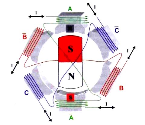
Fig. 4
In these current engines switched electronically and switches the windings of the stator magnetic field makes electromagnets rotor follow his field.
To monitor the current position of the rotor use are encoders or Hall sensor or techno logy voltage measurement anti EMF in windings without use, in this case, an individual gauge Polo provisions rotor (SensorLess ').
Since switching currents of stator windings performs SJ using electronic keys (valves), brushless BLDC motors are often called "supervisor". In this case, the sequence of pairs of windings connection engine la occurs depending on the current situation of Roto RA. When the engine type BLDC controller stator winding coal kommuti so. vector of magnetic field to one hundred Torah is always shifted by an angle close to +90° or -90: regarding the magnetic vector for La rotor. Thus creating by the rotating magnetic field, which causes the move resort followed by rotor with permanent magnets jannymi.
При использовании трехфазного сигнала управления подключенными к источнику тока всегда оказываются только две пары обмоток, а одна – отключена. Таким образом происходит чередование фаз при вращении электродвигателя (рис.5).
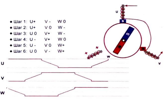
Fig. 5
Such engines without rotor position sensors are different you high manufacturability process manufacturing and low cost, their design uproshha em external sealing connected operational conclusions.
Often, as the speed sensors and rotor position in BLDC used dates Chiki Hall which differ a small cost, but also quite nevyso Kim permission.
Higher resolution delivering LY Rotary transformers (rezolve rea). They are highly valued and require the use of DAC, as the output of the signal sine they Noe Very you high resolution, but low reliability. have optical sensors Output signals of sensors of different types of mort, when rotation of the engine rotor set is shown in Figure 6.
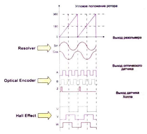
Fig. 6
Advantages of engines BLDC
- the absence of brushes, which provides for the reduction of reliability for vyshennuju spending on maintenance,
- the linearity of current/torque
- high efficiency,
- simplified heat dissipation.
Disadvantages of engines BLDC
- a more complex control system with feedback on the status of the rotor,
- Ripple torque
Stepping motors
Stepper motors are widely used in the Max system automation and control. They represent another type of DC motors that are without collectors.
In stepping motor has a stator, hosts of the field winding and rotor made of magnetic materials. Thanks to the magnetic rotor stepping motor provide more torque and rigid fixation of the rotor when the wires are put in the windings.
In the process of working rotor stepper motor moves steps running for stator winding pulses PI Tania. Stepper motors are suitable for use in machinery drives working in start/stop mode. When you do this, you specify a particular rotor displacement range after dovatelnostju of electrical pulses.
These engines distinguish themselves by high accuracy angular movement, do not require feedback circuits and sensors.
The angle of rotation of the rotor stepping motor sit depends on number of impulse control. The magnitude of the step depends on the design features of DWI be, winding connection diagrams and sequence for governing them.
Stepper motors are divided into bipolar and unipolar, depending on the configuration of the winding connection diagrams.
Bipolar motor has in each of the two phases of a single obmot Ku for both stator poles to which changes the direction of the magnetic field of the perepoljusovyvaetsja driver. I.e., bipolar motor has two windings and responsibly, four output. To control it requires bridge drivers or polumostovaja circuit with bipolar nutrition. When bipolar UE in managing simultaneously operate two windings, that allows the filling level get torque by approximately 40% more. Sequence control signals when rotating bi polar stepper motor is shown in Fig. 7.

Fig. 7
Homopolar motor each phase has one winding with average output and allows you to use a simpler control scheme with one key for each blow of the four poluobmotok. Containing 4 stepper motor windings can be used for both bipolar and unipoljar Noi configuration.
When current flows through a coil, a rotor shoot to capitalize on change position so that the opposite rotor and stator Luce established against each other. Ta Kim way, for continuous rotation of the rotor coils alternately switch.
Use different methods of presenting Pete at four of the stator winding. Usually apply popar Noe connecting with polnoshagovym or polushagovym Régis IOM work.
In popnoshagovom mode rotor with two poles, spinning in NE rekljuchaemom magnetic field two pairs of coils, can take less than four Che position (fig. 8).
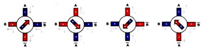
Fig. 8
To achieve the double dot Ness positioning and AC tion eight positions used polushagovyj mode of operation (fig. 9). To provide this intermediate step is added with simultaneous Noah zapitkoj all four coils.
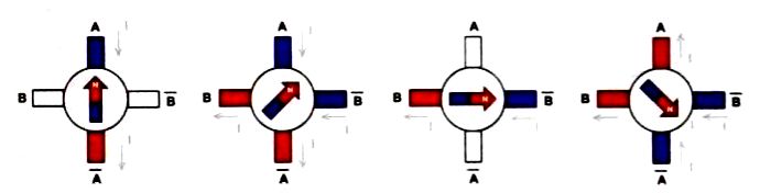
Fig. 9
Mikroshaga mode uses Xia to obtain even greater productivity point positioning.
This mode is provided by giving the stepper motor windings rather than control pulses continuous signal, resembling in form stepped sine curve.
Thus, the stepper motor full step is divided into small MI kroshagi, and his rotation becomes smoother. Names but mikroshaga mode allows you to get the most accurate by zicionirovanie. Besides. in this mode significantly reduces the inherent vibration engines stepper chassis.
Dignity of stepper motors:
- high positioning accuracy;
- good holding time;
- a wide range of speeds;
- low cost due to the absence of schemes Cohn ing the rotation speed and positioning;
- a simple management interface with digital kontrolle Rami;
- very high reliability.
Disadvantages of stepper motors:
- quite complex control scheme; energy consumption does not decrease even when running without load;
- due to the lack of feedback possible loss con diley provisions; low power;
- SHD inherent resonance phenomenon;
- difficult work at very high speeds.
Mikroshaga mode illustrates the figure 10.

Fig. 10
Standard solutions for motor control
Traditional precision systems for motor control Ma constant current includes Mick rokontroller data-processing and power control unit windings DWI be (driver). The driver contains an extraordinary scheme to convert the Lo Ko dirovannyh parcels in the digital office develop signals. Of these signals in the block Gate Driver formed similar trade signals for power management keys performed on FET (FET), which may be included in the driver or be placed in a separate block. The composition also includes driver protection circuit and power circuit feedback loop to control the operation of the engine.
Functional options schemes for integrated and prior for driver shown in Fig. 11. Each of these schemes has its advantages and features. Pre preliminary drivers (Pre-Driver, fig. 11) has a great but man in heat mode that allows you to select the external power keys in accordance with a capacity under kljuchaemogo to the device of the motor.
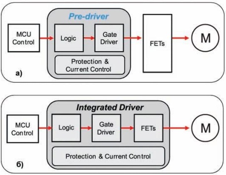
Fig. 11
A full-featured integrated driver (fig. 11, b) allows you to create more compact management system minimizes external connections, but misses the sophistication to ensure heat dissipation and struggle with overheating of the individual elements of the device.
For example, the prior driver from company TI DRV8301 type the maximum operating temperature of individual items on board does not exceed 37° c, while the integrated driver type DRV8312 this figure may be as high as 100° c.
Мост типа «Н» – это одна из наиболее распространенных схем для коммутации обмоток электродвигателей. Такое название схемы связано с конфигурацией подключения, которая похожа на букву «Н».
This electronic circuit allows you to easily change the current Board in load and, hence, the direction of rotation of the rotor of electric motor collector.
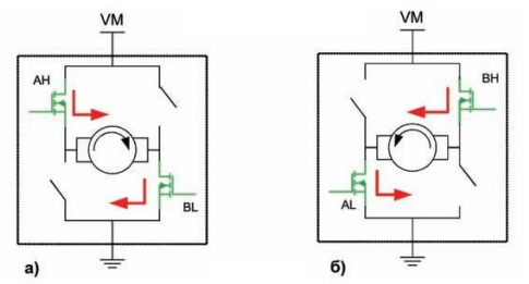
Fig. 12
The voltage applied to the windings through Tran zistory bridge, can be both permanent and MO dulirovannym by using a SHIM. "H" bridge is necessary, first of all, to change the direction of rotation of the motor (reverse) by changing the polarity of Pete tion motor (fig. 12), but it also allows you to reduce the braking engine, briefly closing conclusions windings (fig. 13).
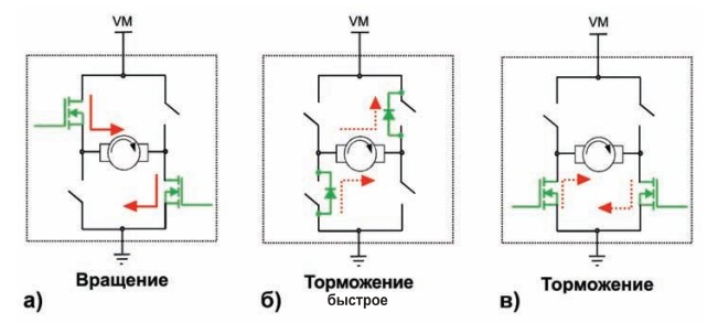
Fig. 13
The most important characteristic of the power bridge elements (usually MOSFETs with izoliro bathrooms gate) is the resistance value of the indoor channel between the source and drain transistor Rdson. The Value Of Rdson determines the heat travel characteristics the control unit motor and energy losses. With increasing temperature (R)dson growing, i.e. current and voltage to the windings of electric rodvigatelja will decrease.
To reduce torque ripple and baking more smooth rotor engine IP enjoyed PWM control signals with a frequency of 20 kHz, more Bo to avoid acoustic noise. One to grow with increasing frequency, loss on tranzisto rah bridge in the process of switching.
Since the motor windings are a complex workload with considerable induktiv Noah component, current in them is not an appropriate voltage PWM form EM. After speeches on impulse control coil current is growing gradually, but in pauses he smoothly subsides due to dispute arose in windings anti-EMF. Rise/fall speed of the current in the winding, the amplitude and frequency of the ripple effect on working characteristics of CI engine: ripple krutjashhe th moment, noise, power, etc.
Three States bridge: working, quick braking (Fast Decay) and slow braking (Slow Decay) shown in Fig. 13.
To accelerate current attenuation in windings of electric rodvigatelej caused by the effectiveness of that anti-EMF using DIO day reverse inclusion, bypassing veying transitions "drain-source» transistors (fig. 13, b). Also zakorachivajut winding through re moves "drain-source" of two transistors, simultaneously included in different shoulders bridge (fig. 13).
It is considered the most effective combined re press (Mixed Decay). In this case, the pause between the operational work first impulses MI diodes, drain-source shunt transistors, and then includes transistors INIM them shoulders.
Drivers to control electric motors
TI offers a wide range of different Motors management drivers tion DC. When using the minimum external com ponent, these drivers allow you to create compact re decision to control engines with working voltage it to 60 in differed construction ensure enhanced reliability, quick and simple engineering systems drive electric motors.
Due to the fact that the drivers are embedded intellectual functions, requires only minimal support for Ext him managing the microcontroller (MCU), and they provide an extended opportunity for switching on Motoc, supported by external sensors and digital control loops.
The composition of the protective functions of the driver include:
- current protection and short circuit protection;
- voltage limit;
- under voltage protection;
- protection against exceeding the maximum working temperature.
In the proposals TI market drivers for DC motors are divided into 3 categories:
- stepper motors;
- commutator motors;
- brushless motors.
In addition, there are separate drivers for use with different types of engines.
Drivers for stepper motors
TI driver classification for controlling stepper motors, see fig. 14. These drivers you will be admitted as with built-in power FET-based keys, and in the form of preliminary tional drivers give the Seaway user selection necessary required power keys. In congenital TI's series Mo Bo 35 more drivers for the MOTOR.
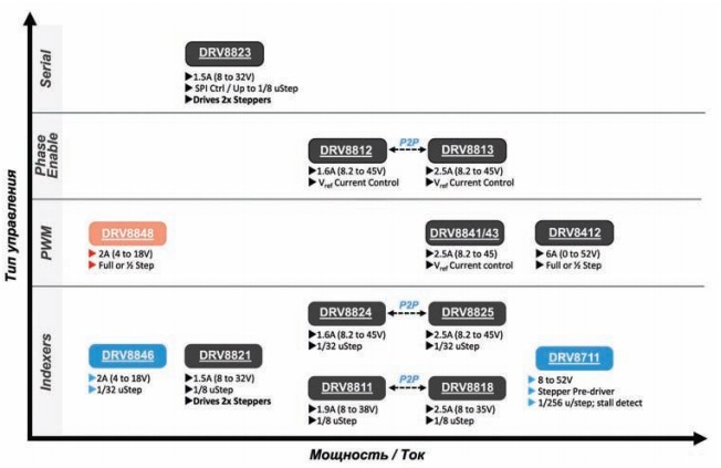
Fig. 14
Drivers for stepper motors use are the most modern solutions for managing re meshheniem and exact positional overwhelming using mikroshagovyh control schemes, providing electric engines bringing wide cance smoother study on range and power.
Some drivers, to some, there is only one yn ravljajushhij controller allows more control two engines with this built-in Bridge less than four Che OS Nove FET. On fig. 15 shows how to use the DRV8834 type driver that can be under items to control two stepper motor windings or use these same you water to control two DC motors.

Fig. 15
To provide a very smooth move rotor MOTOR drivers used custom anti-aliasing mechanism of current pulses (Slow, Fast, Mixed Decay).
Used 2 mikroshaga calculation options:
- using an external reference signal;
- system built into the drivers.
- Drivers types DRV8812, DRV8813, DRV8828, DRV8829, DRV8841, DRV8842 and DRV8843 provide mikroshagovoe rotation with the use of an external con trollera reference voltage (Vref). The level of fragmentation of the primary OS step can achieve the value 1/128 or 1/256.
- Drivers types DRV881, DRV8818, DRV8821, DRV8824 and DRV8825 do not require an external controller for mikroshagovogo move. They move and step switching algorithm tings windings are calculated scheme built into the drivers.
Drivers types DRV8803, DRV8805 and DRV8806 are designed for MOTOR control with unipolar is connected with the exception of the windings.
Drivers for collector Motors (BOC)
Специальное семейство драйверов DRV8х предназначено для управления коллекторными электродвигателями постоянного тока. Классификация представителей этого семейства показана на рис.16. Эти драйверы обеспечивают защиту двигателя от: короткого замыкания, превышения напряжения и тока, перегрева.

Fig. 16
С помощью одного драйвера можно управлять одним или несколькими двигателями с рабочим напряжением 1.8…60 В. Среди драйверов этого семейства есть драйверы как с интегрированными силовыми ключами, так и драйверы требующие использования внешних ключей.
In General, drivers of the CE mejstva require a minimum of external controls that provide com paktnost solutions that reduce development time and allow you to quickly release new products you market.
To minimize energy consumption requirements in idle mode and provides accelerated Akti increased when the engine is running, these drivers use Hibernate (Sleep).
To select the direction of rotation and inclusion of key whose output bridge can be used AC signal PHASE whitefish/ENABLE. Control soon Stu rotation can be used AC PWM signals.
Driver type DRV8823 contains four weekend bridge and manage current SPI interface. Therefore, it can but used to control the MOTOR ring, or TLDs one MOTOR and two or four BDC BDC.
Functional diagram driver DRV8837 managing a collective reflex motor is shown in Fig. 17.
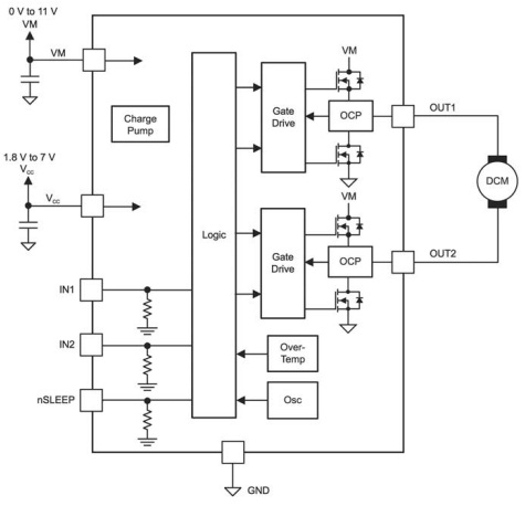
Fig. 17
Drivers for motors that are without collectors (BLDC)
TI drivers for BLDC may include integrated power bridge or use external silo new transistors. In this diagram the formation of 3-phases ERS control signals can also be external or internal.
Family management drivers BLDC include insufficient models with different torque and with different principles of governance. Before drivers are assigned for use in industrial equipment requirements, automotive systems and other equipment.
Protect drivers from exceeding the current, voltage and temperatures, however.
Classification of some of the 3-phase drivers TI for BLDC enforceability on the Fig. 18. The lineup of dry applications that constantly flowed family.
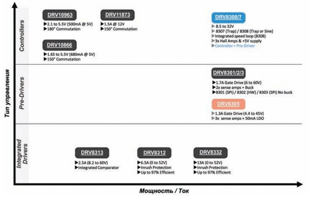
Fig. 18
Drivers for BLDC rotor position monitoring is carried out either by using a control scheme with the determination of position of rotor ve locking anti-EMF (Electromotive Force Back BEMF) or using external sensors of different types.
Frequency control and swing, erasing a rotation engine Pro data will be decrypted! using PWM, Ana logovyh signals or through Nye standard digital interfaces.
To store custom PA lect internal non-volatile memory.
Функциональная схема интеллектуального драйвера для BLDC типа DRV10983 со встроенными силовыми ключами на полевых транзисторах, с сопротивлением открытого канала всего лишь 250 мОм приведена на рис.19. Этот драйвер может работать в широком диапазоне температур от -40°С до +125°С и в диапазоне рабочих напряжений 8…28 В драйвер может обеспечивать номинальный ток 2 А (пиковый ток 3 А).

Fig. 19
Драйвер не требует внешнего датчика для контроля положения ротора, но может использовать внешний резистор для контроля потребляемой двигателем мощности. Достоинство драйвера – это малая потребляемая мощность, ток потребления в дежурном режиме составляет всего 3 мА. В энергосберегающей модели DRV10983Z этот показатель доведен до уровня 180 мкА. Через интерфейс I2To provide Diagnostics and for construction, access to the registers of the population management work of the logical schema and stored in EEPROM memory RA bochim driver profiles.
Driver for shhitnyh has a wide range of functions:
- stop the engine in case of excess current and voltage;
- input voltage limit;
- excess current protection works without use MOUS tion external resistor.
There are special registers for setting the motor protection techniques use IU.
Author: Alexey Zotov, Kursk
Source: Electrician No. 3, No. 4/2017