Регулировать напряжение мощного нагрузке удобно с помощью регуляторов с широтно-импульсной модуляцией. Преимущество таких регуляторов заключается в том, что выходной транзистор работает в ключевом режиме, а значит имеет два состояния – открытый или закрытый. Известно, что наибольший нагрев транзистора происходит в полуоткрытом состоянии и требует установки его на радиатор.
It's a simple diagram of the PWM controller is powered from a source 12V (max current 10A).
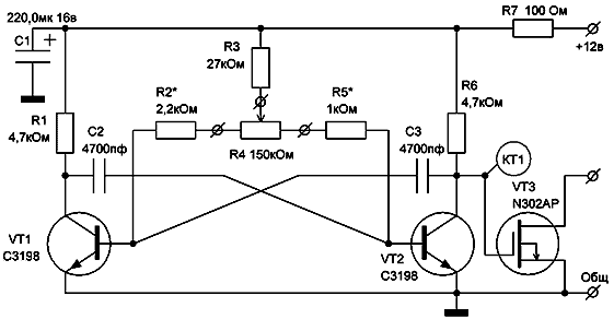
Simple adjustable PWM
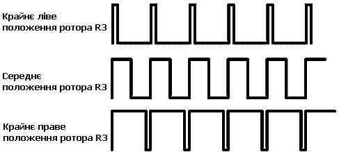
Transistors VT1 and VT2 constitute a multivibrator with adjustable duty cycle and frequency ~ 7кГц. With the collector VT2 pulses are applied to the switching transistor VT3, which controls the load. The duty cycle is regulated by a variable resistor R4:
1. при крайнем левом положении ротора – импульсы на выходе устройства узкие (минимальная мощность)
2. при крайнем правом положении – импульсы широкие (полная мощность)
Simple adjustable PWM
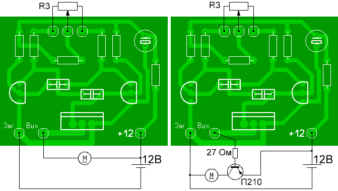
This controller can control devices with a 12V supply (12 V filament lamp, DC motor with an insulated housing, etc.). In the case of the use of the regulator in the car, where the negative is connected to the housing, connected via a pnp transistor.
Simple adjustable PWM
Connectivity options
The generator can operate with virtually any low-frequency transistors, such as KT315, КТ3102. The key transistor IRF3205, IRF9530. If the pnp transistor П210 replace КТ825, then the maximum load current will be 20A!
 Simple adjustable PWM
Photo devices
Author: Gilfanov A. M. Kushva