In this article I will tell how from the computer power supply format at/ATX and self-made control unit to manufacture a pretty "smart" charger for lead-acid batteries. These include the so-called "oops marketing", automotive and other battery wide application.
Description
The device is intended for charging and training (desulfatation) lead-acid batteries with a capacity from 7 up to 100 Ah, and a rough estimate of their remaining charge and capacity. The memory is protected against incorrect switching batteries (polarity reversal) and short-circuit accidentally abandoned terminals. It adopts microcontroller control, due to which are safe and optimal algorithms of charging IUoU or IUIoU, followed by "sweeper" to 100% charge level. The charge parameters can be adjusted to suit a particular battery (customizable profiles) or choose already incorporated in the control program. Structurally, the charger consists of power supply at/ATX, which should be modified and the control unit at MK ATmega16A. The entire device is freely mounted in the housing of the same power supply. Cooling system (a standard cooler power supply) can be enabled/disabled automatically.
The advantages of this memory — its relative simplicity and absence of time-consuming adjustments, which is especially important for novice radio Amateurs.
1. Charging mode — menu "Charge". For batteries with capacities from 7Ah to 12Ач the default algorithm IUoU. This means:
— the first stage - charging steady current of 0.1 C until напряжения14.6V
— the second phase-charge voltage 14.6 V until current drops to 0.02
third step — maintaining a stable voltage 13.8 V until the current drops to 0.01 C. Here C is the capacitance of the battery in Ah.
— the fourth stage — the "sweepers". At this stage tracks the voltage at the battery. If it drops below 12.7 V, charge enabled from the start.
For starter battery (45 Ah and higher) the applied algorithm IUIoU. Is the third stage included the stabilization of the current at 0.02 C until the voltage on the battery 16B or the passage of time, about 2 hours. At the end of this phase, the charging starts and stops the "sweepers". This is the fourth stage. The charge process is illustrated by the graphs Fig.1 and Fig.2.
2. Training mode (desulfatation) menu "Training". Here is the training cycle:
10 seconds is the discharge current of 0.01 C, 5 seconds — charge current of 0.1 C. the charge-discharge cycle continues until the voltage of battery rise up to 14.6 V. Further — ordinary charge.
3. Mode the battery test. Allows to estimate the degree of discharge. The battery is loaded with current of 0.01 to 15 seconds, then switched to measure the voltage on the battery.
4. Control-training cycle (CWC). If you connect a load to turn on the "Charge" or "Training", in this case, first perform the discharging of the battery to a voltage of 10.8 V, and then turns on the appropriate mode is selected. Thus the measured current and the discharge time, therefore, calculated the approximate capacity of the battery. These options appear in the display after charging (when you see the "Battery charged") by clicking on the button "select". As additional load you can use a car bulb. Its capacity depends on the required discharge current. It is usually set equal to 0.1 S — 0.05 S (the current 10-year or 20-hour discharge).
Navigating the menus is accomplished with the buttons "left", "right", "choice". The button "reset" is output from any mode of operation of the memory main menu.
The main parameters of the charging algorithm can be customized for a particular battery, in this menu there are two custom profile is P1 and P2. The configured settings are stored in nonvolatile memory (EEPROM).
To get into the settings menu you need to choose any profile, press "select", choose "settings", "settings profile", the profile P1 or P2. After selecting the desired option, press select. Arrows "left" or "right" change the arrows "up" or "down", which means the readiness of the parameter to change. Select the desired setting by pressing "left" or "right", confirmed by the button "select". The display will show "Saved", which means write value to EEPROM.
The values of the settings:
1. "Algorithm of charge". Selected IUoU or IUIoU. Cm. the graphs in Fig.1 and Fig.2.
2. "The battery capacity". When setting this parameter, we set the charge current at the first stage, I=0.1 C, where C is the battery capacity In Ah. (Thus, if you need to specify the charge current, for example, 4.5 A, you should choose the battery capacity 45Ач).
3. "Voltage U1". This is the voltage at which the first stage charging and starts the second. The default is set to 14.6 V.
4. "Voltage U2". Is used only if you specify algorithm IUIoU. This is the voltage at which ends the third stage of charging. Default — 16V.
5. "The current of the 2nd stage I2". This value of current at which ends the second stage of charging. The current stabilization in the third stage to the algorithm IUIoU. The default value of 0.2 C.
6. "The end of the charge I3". This value of current, which the charging is ended. The default value is 0.01 S.
7. The "discharge current". This value of current, which is the discharge when training the charge-discharge cycles.


Selection and alteration of the power supply.
In our design we use the power supply from the computer. Why? There are several reasons. First, it is virtually ready for the power part. Secondly, this is also the case of our future devices. Thirdly, it has a small size and weight. And fourth, it can be bought on virtually any radio market, flea market and computer service centers. As they say, cheap and cheerful.
From the variety of models of power supplies we are best suited block size ATX, power not less than 250 watts. You only need to consider the following. Only those power supply units that apply the PWM-controller TL494 or its analogues (MB3759, КА7500, КР1114ЕУ4). Can also be used AT BP format, only have to make a low power unit, the standby power unit (duty room) for a voltage of 12V and a current of 150-200mA. The difference between AT and ATX – the scheme of the initial launch. At run on its own, the power of the chip PWM controller is taken from the 12-volt winding of the transformer. In ATX for the initial power chip is a separate 5V source, called "standby power source" or "guardroom".
So, the power supply is available. First, it is necessary to check for serviceability. To do this, dismantle it, take out the fuse and instead podpaivaem lamp bulbs 220-volt power 100-200W. If on the rear panel of the PSU there is a switch in the mains voltage, it should be set to 220V.
Include BP in the network. The power supply at start, it is necessary to short the ATX green and black wires on the big connector. If the bulb is not lit, the cooler spinning and all output voltages OK — so we were lucky and our power supply is working. Otherwise, have to deal with it. Leave the light bulb is still in place.
For the alteration of BP in our future charger, we will need to slightly change the "binding" of the PWM controller. Despite the huge diversity of the power supply circuits, the switching circuit TL494 standard and may have a few variations, depending on how the team implemented the protection of over current and limit voltage. The scheme of alteration is shown in Fig.3.

It shows only one channel of output voltage: +12V. Other channels: +5V,-5V, +3.3 V not used. They definitely need to disable by cutting the appropriate track or vypav of their chain elements. Which, by the way, we can be useful for the control unit. More on that — later. Red indicates items that are optional. Capacitor C2 should have a working voltage not lower than 35V and installed to replace the existing PSU. After "tying" TL494 given to the scheme in Fig.3 to be included in the BP network. The voltage at the output of the PSU is determined by the formula: VOUT=2,5*(1+R3/R4) and, if specified in the diagram values should be about 10V. If not, will have to check the correctness of installation. The alteration is finished, you can remove the bulb and put in place of the fuse.
Diagram and working principle.
Diagram of the control unit shown in Fig.4.

Она довольно проста, так как все основные процессы выполняет микроконтроллер. В его память записывается управляющая программа, в которой и заложены все алгоритмы. Управление блоком питания осуществляется с помощью ШИМ с вывода PD7 МК и простейшего ЦАП на элементах R4,C9,R7,C11. Измерение напряжения АКБ и зарядного тока осуществляется средствами самого микроконтроллера — встроенным АЦП и управляемым дифференциальным усилителем. Напряжение АКБ на вход АЦП подается с делителя R10R11, Зарядный и разрядный ток измеряются следующим образом. Падение напряжения с измерительного резистора R8 через делители R5R6R10R11 подается на усилительный каскад, который находится внутри МК и подключен к выводам PA2, PA3. Коэффициент его усиления устанавливается программно, в зависимости от измеряемого тока. Для токов меньше 1А коэффициент усиления (КУ) задается равным 200, для токов выше 1А КУ=10. Вся информация выводится на ЖКИ, подключенный к портам РВ1-РВ7 по четырёхпроводной шине. Защита от переполюсовки выполнена на транзисторе Т1, сигнализация неправильного подключения — на элементах VD1,EP1 ,R13. При включении зарядного устройства в сеть транзистор Т1 закрыт низким уровнем с порта РС5, и АКБ отключена от зарядного устройства. Подключается она только при выборе в меню типа АКБ и режима работы ЗУ. Этим обеспечивается также отсутствие искрения при подключении батареи. При попытке подключить аккумулятор в неправильной полярности сработает зуммер ЕР1 и красный светодиод VD1, сигнализируя о возможной аварии. В процессе заряда постоянно контролируется зарядный ток. Если он станет равным нулю (сняли клеммы с АКБ), устройство автоматически переходит в главное меню, останавливая заряд и отключая батарею. Транзистор Т2 и резистор R12 образуют разрядную цепь, которая участвует в зарядно-разрядном цикле десульфатирующего заряда (режим тренировки) и в режиме теста АКБ. Ток разряда 0.01С задается с помощью ШИМ с порта PD5. Кулер автоматически выключается, когда ток заряда падает ниже 1,8А. Управляет кулером порт PD4 и транзистор VT1.
Details and design.
Microcontroller. Sales usually occur in the case of the DIP-40 or TQFP-44 and labeled as: АТМеда16А-or PU ATMega16A-AU. The letter after the hyphen denotes the type of the case: P - DIP case, "A"- TQFP. There are also discontinued microcontrollers ATMega16-16PU, ATMega16-16AU or ATMega16L-8AU. In them, the number after the dash indicates maximum clock frequency of the controller. Manufacturer ATMEL recommends using ATMega16A controller (with the letter "a") and TQFP, i.e., these are: ATMega16A-AU, although our device will work all of the above instances, and confirmed that the practice. The types of buildings differ also by the number of terminals (40 or 44). In Fig.4 is a schematic diagram of the control unit for MK in the housing DIP.
Resistor R8 –ceramic, or wire, of a power less than 10 W, R12 - 7-10W. All the rest - 0.125 watts. Resistors R5,R6,R10 and R11 need to be applied with a tolerance of 0.1-0.5%. This is very important! This will depend on the accuracy of measurements and consequently, proper operation of the entire device.
Transistors T1 and T1 to be desirable, such as shown in the diagram. But if I have to find a replacement, it is necessary to take into account that they should open voltage of the gate is 5V and, of course, must withstand the current below 10A. Suitable, for example, transistors with marking 40N03GР, which are sometimes used in the same BP size ATX, in the regulation circuit 3.3 V.
The Schottky barrier diode D2 can be taken from the same PSU, the +5V circuit, which we have not used. The elements D2, T1 иТ2 through the insulating gasket placed on a radiator with an area of 40 square centimeters. The buzzer EP1 - generator voltage is 8-12 V, the sound volume can be adjusted by the resistor R13.
Liquid crystal display – WH1602 or equivalent controller HD44780, KS0066 or compatible with them. Unfortunately, these indicators may have different Pinout, so you may have to develop the PCB for your instance
Program
The control program contains in the folder "Program" Configuration bits (fuse) are set as follows:
Programmed (set to 0):
CKSEL0
CKSEL1
CKSEL3
SPIEN
SUT0
BODEN
BODLEVEL
BOOTSZ0
BOOTSZ1
all the rest — unprogrammed (set to 1).
Setting up
So, the power supply is redone and gives a voltage of about 10V. When it is connected to proper control unit with stitched MK, the voltage should drop to 0.8..15V. Resistor R1 sets the contrast indicator. The adjustment device is in the verification and calibration of measuring parts. Connected to the terminals of the battery or the power supply voltage of 12-15V voltmeter. Go to the menu "Calibration". Compare the voltage readings on the gauge with the voltmeter, if necessary, adjusted by the buttons "<" and ">". Press "Select". Next is the calibration current if KU=10. The same buttons "<" and ">" need to set the zero reading of current. The load (battery) switches off automatically, so that the charge current is missing. Ideally, there should be zeros or very close to zero values. If so, this says about the accuracy of the resistors R5,R6,R10,R11,R8 and good quality of the differential amplifier. Press "Select". Similarly, the calibration for gain=200. Select. The display shows "Ready" and after 3 sec. the unit will go into the main menu.
Calibration is done. Correction factors are stored in nonvolatile memory. It is worth noting that if the first calibration voltage value on LCD differs from the readings of the voltmeter and currents at any KU differ from zero, you need to use (to select) the other resistor of the divider R5,R6,R10,R11,R8, otherwise the device may not function properly. When accurate resistors (tolerance of 0.1-0.5%), the correction factors are equal to zero or minimum. This adjustment ends. If the voltage or current charger at some point does not increase to the normal level or device "popping up" in the menu, you need to once again carefully verify the correct revision of the power supply. Perhaps, in protection.
Архив к проекту:
[hidepost] Download [/hidepost].
And finally, a few photos.
The location of the elements in the housing of the power supply:
 Finished design might look like this:
so:

or even so: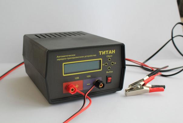
I will try again
the scheme works well.the charger itself is built and tested.
video on my channel in YouTube.
http://www.youtube.com/watch?v=eGP8f1RuRdo
Hello everybody. Charger works well but there is little nuance. When calibrating voltage current is absent and hence no drop in the wires, so increasing the current charge voltage on the display and the tester begin to differ. Question to author: is it possible to control the voltage on the battery to produce a free port of the processor, respectively, by additional wires to the battery?