In our century of progress from any Amateur radio is the main unit when the setting device is a laboratory power supply unit (PSU). BP can be both homemade and factory performance. Vary in complexity, can be all assembled in one linear voltage regulator such as LM317T, can be assembled on operational amplifiers, transistors. BP can be protected against short circuit, or Vice versa, adjustable limit output current. A better PSU have switch mode "short circuit Protection/output current Limiting". But almost all power supplies are equipped in the best case, a needle voltmeter. A digital voltmeter is complicated to manufacture and configure, and often requires the use of specialized circuits of the ADC, for example, КР572ПВ2А.
But the whole difficulty lies not in making payment, and you need bipolar power supply +5V, -5V to supply the specified chip. This requires a separate low-power PSU or a separate winding of the transformer. Thus, the ADC data is not really proven themselves in the Amateur practice. What happens? In the XXI-St century, but Amateur design BP did not affect the progress? You must fix this situation! Thinking about this, I came to the conclusion that it is necessary to make your own display device parameters power supply for the microcontroller. In this regard, and has developed a module – digital multi-meter. Which will be discussed later in more detail. This development is proposed to repeat and possible refinement, as it is done in a pilot version and needs to be improved..(Planned feature power estimation and display on the indicator, but have not reached the hands, and when testing discovered bugs in the current measurement.) But even in this scenario, this scheme is quite efficient and may be asked to repeat, even for novice hams. The main emphasis was on keeping a minimal complexity so as not to leave behind beginner radio Amateurs. That's what I did.
Схема:
The device provides the following parameters and functions:
1. Measurement and indication of the output voltage of the power supply in the range from 0 to 100V, with a resolution of 0.01 V
2. Measurement and indication of the output load current of the power supply in the range from 0 to 10A with 10mA resolution
3. Measurement error not worse than ±0.01 V (voltage) or ±10mA (current)
4. Switching between measurement modes voltage/current by using the buttons in the depressed position.
5. The output of measurement results on the large four-digit display. In this case, three digits are used to display measured values, and the fourth to indicate the current measurement mode.
6. A feature of my multi-meter automatically selects the limit of measurement. The point is that voltage 0-10V is displayed with an accuracy of 0.01 V, and voltage of 10-100V with accuracy of 0.1 V.
7. Really a voltage divider designed with a margin, when the measured voltage increases more 110V (well, maybe someone has less, it is possible to fix this in the firmware), the indicator shows overload – O. L (Over Load). Similarly done with the ammeter, if exceeded, the measured current is greater than 11A voltammeter goes to the display mode of the overload.
The device provides measurement and display only positive values of voltage and current, and for current measurement used shunt circuit "minus".
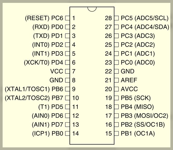
The device is implemented on the microcontroller DD1 (IC) ATMega8-16PU.
Technical parameters ATMEGA8-16PU:
Ядро AVR
The bit width of 8
Clock frequency, MHz 16
Volume ROM-memory 8K
The amount of RAM-memory 1K
Internal ADC number of channels 23
Internal DAC number of channels 23
Timer 3 channel
Supply voltage 4.5...5.5
Температурный диапазон, C 40…+85
Body type DIP28
The number of additional circuit elements is minimal. (More complete data on MK you can learn from dataset on it). The resistors in the diagram — type MLT-0,125 or imported analogues, electrolytic capacitor type K50-35 or similar, the voltage of at least 6.3 V, capacity of it can differ in a big way. Capacitor 0.1 UF ceramic imported. Instead DA1 7805 you can use all the analogues. The maximum supply voltage of the device is determined by the maximum allowable input voltage of this chip. About the type of indicators discussed later on. During processing of the printed circuit Board is possible to use other types of components, including SMD.
Resistor R... imported ceramic, resistance 0.1 Ohm 5W, you can use more powerful resistors, if the dimensions of the seals allow to set.You also need to examine the scheme of constant current PSU, perhaps there is already a current resistor of 0.1 Ohm in the negative bus. You can use the this resistor. To power the device can be used either as a separate regulated power supply +5V (then chip voltage regulator DA1 is not needed), or unregulated source of +7...30V (with mandatory use of DA1). Consumed by the device current does not exceed 80mA. You should pay attention to the fact that the stability of the supply voltage indirectly affects the measurement accuracy current and voltage. Indication — a common dynamic, at some point in time illuminates only one category, but because of the inertia of our vision we see glowing all four lights and perceived as a normal number.
Used one current limiting resistor for a single led and refused the need for additional transistor switches, since the maximum current port MK in the scheme does not exceed 40 mA. By changing the program, it is possible to implement the possibility of using indicators as a common anode and a common cathode. Type indicators can be any — both domestic and imported. In my version, applied double indicators VQE-23 green glowing digits height 12 mm (it's ancient, little-bright LEDs found in the old stockpile). Here are the technical data for reference;
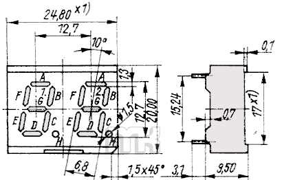
Indicator VQE23, 20x25mm, OK, green
Two-digit 7-segment indicator.
Type Common cathode
Color: green (565nm)
Brightness 460-1560uCd
Decimal point 2
Rated current 20mA segment
Below are the Pinout and outline drawing of the indicator:
 1. Anode H1
2. Anode G1
3. The Anode A1
4. Anode F1
5. Anode B1
6. Anode B2
7. Anode F2
8. The Anode A2
9. Anode G2
10. Anode H2
11. The Anode C2
12. The Anode E2
13. Anode D2
14. Common cathode K2
15. Common cathode K1
16. Anode D1
17. Anode E1
18. Anode C1
It is possible to use any indicators as one-, two-, and four-digit common cathode, will have only the PCB Board for them to do. Board made from double-sided foil fiberglass, but maybe the use of unilateral, just need a few jumpers to solder. The elements on the Board are set on both sides, therefore, the order of Assembly:
• First, you need to solder jumpers (vias), which is a lot under the LEDs and near the microcontroller.
• Then the microcontroller DD1. You can use the collet socket, thus it must be set not to lock in the fee, so you can solder the insights from the chip. Because it was not under the paw of the Chuck socket, it was decided to solder the IC firmly in charge. For beginners I do not recommend, in the case of a failed firmware 28-nogi MK is very inconvenient to replace.
• Then all other items.
Operation of this module of the multi-meter does not require explanation. Quite correctly connect the power supply and measuring circuit. Open cardigan or button – voltage measurement, a closed sweater or button – current measurement. The firmware can hold the controller in any way. Of Fuse-bits that you need to do is enable the built-in generator 4 MHz. Nothing terrible will happen if they do not flash, just MK will work at 1 MHz and the numbers on the display will flicker badly.
And here is the photo multi-meter:
 I can't give specific recommendations, in addition to the above, on how to connect the device to a particular circuit of the power supply — after all, just many of them. I hope this task will really be so easy as I imagine.
Archive Project
All questions to ask forum

