 Устройство (назову его “VTC”), представленное в этом проекте, содержит в себе функции 3-х устройств: вольтметр, термометр и часы. Выполнено оно на микроконтроллере семейства AVR ATMega8.
Funcionalno VTC operates in one mode, which is selected by pressing the button:
Digital voltmeter You can measure DC voltages from 0 to 25 volts. ATMEGA8 is used as a controller, which taktuetsja the internal RC-generator 8 MHz. DC voltage measurements are made using the built-in controller and 10 bit ADC. Measured voltage divider through R9, R10 arrives at the entrance ADC0 (PortC. 0 p. 23). After the change, the measurement result is displayed on the 4-th bit indicator with common anode (in my case, RL-C5620). Pay attention that they are of different sizes may vary cokolevkoj and inclusion (OA and OK).
Thermometer allows you to measure the teperaturu from -50 to + 85 gadusov. I would like to point out that because the temperature indication given 3 digits, then tenths of displayed only in the range − 9.9. +85° c, and temperatures are displayed without tenths. At temperature from -10 and lower decile more than 0.5 degrees is shown by the inclusion of a point (as in the fourth picture below).
 |
Room temperature |
 |
“плюсовая” температура, погашен незначащий ноль |
 |
temperatures below zero |
 |
Temperature-12.5 degrees |
 |
Such maximum low temperature I managed to measure (in the freezer the fridge) |

Переключение между режимами вольтметра и термометра производится кнопкой S1: один раз нажали – вольтметр, ещё раз – термометр, ещё раз -часы и так по кругу.
Supervisory radio amateur may notice connection mismatch digits indicator. The thing is that the 3-rd level indicator are two points that need them for hours and they are here isspolzujutsja only in clock mode. So I concluded in the program information first on the first level, then 2nd, 4th, 5th and then 3 (only if the clock mode).
Buttons management connected to seemingly have the same busy indicator the port, but it is, there is no error. Let me explain: once happen at all output serial digits port switches direction, i.e. becomes entrance and scans the existence of pressed buttons, and then changes direction and becomes the port output. This process is repeated again and again.

| vtc.rar [185.23 Kb] (count: 713) | The firmware on the controller. |
| vtc_n.rar [176.61 Kb] (count: 501) | Прошивка контроллера с сигнализацией гололеда: при температуре от +1 до -3 градуса, моргает значек “градус”, привлекая тем самым дополнительное внимание. |
| vtc-1_v2.2b.rar [28.58 Kb] (count: 519) | Firmware version v2.2b In this version of voltage measurement up to 40 volts |
| vtc-1-v2.2p.rar [18.38 MB] (count: 151) | Firmware version v2.2p By popular demand, firmware which in clock mode blinks separating comma (for those who did not manage to find the time indicator) |
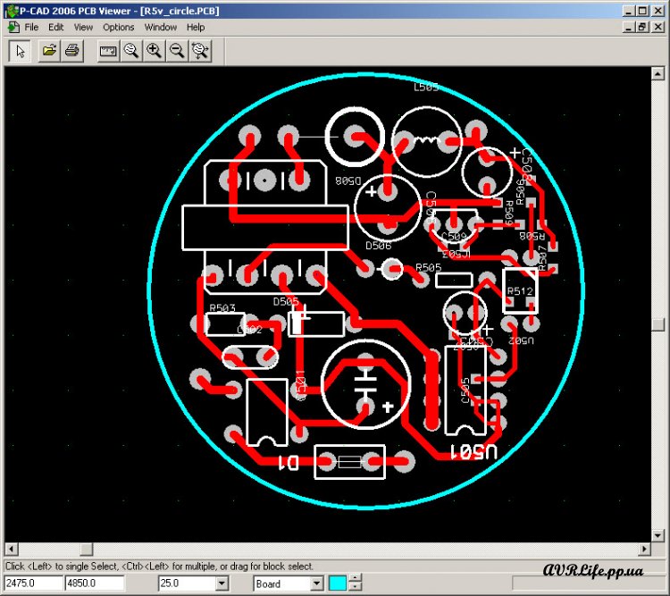
| pcb_vtc-1.rar [161.87 Kb] (count: 614) | PCB format P-CAD. |
| pcb_igumich.rar [13.28 Kb] (count: 271) | PCB Layout format for IC DIP package |
| pcb_boba.rar [31.9 MB] (count: 264) | PCB Layout format for IC DIP package |
I put this device in the power supply. It is very convenient. Here's the video:
Dear customers with this project with MK in DIP package, if you would like to share their version of the printed circuit board, share in the comments references, files, or images.
All questions to ask forum
первоисточник avrlife.pp.ua
WordPress database error: [Table './meandr_base/anzpz_usermeta' is marked as crashed and last (automatic?) repair failed]
SELECT user_id, meta_key, meta_value FROM anzpz_usermeta WHERE user_id IN (1973) ORDER BY umeta_id ASC