У многих радиолюбителей “со стажем” сохранились запасы морально устаревших, но вполне работоспособных микросхем и других деталей. Но прямая замена ими современных элементов зачастую не даёт положительных результатов. Автор рассказывает, как он решил возникающие проблемы при повторении известных конструкций сенсорных выключателей.
I want to return to a subject that has been raised on pages jour NALA. This sensor switches, Rea girujushhie at the touch of your hands to Saint sornomu contact. Generally, touch switch is a very good thing, especially if it is compact. It can be embedded in many household appliances and enable/disable them when kosnoveniem finger to the metal parts of the body (sometimes it can be invisible).
The most suitable Sep weeds switches, controlled by touching a single sensor. Such constructions, built on a series of chips to 561, described, for example, [1] and [2]. Many radiolju users still have stocks of functionally similar, but morals but obsolete 176 series chipset. However, attempts to simply replace the chip designs to 561 series have not led to positive results ensue.
Recently I needed a few touch switches sound transmitters Lei, and were available only mikroshe we to 176 176 Tm1 and Tm2. Buy ad specially for switches to chip 561 Tm2 didn't want to, so it was decided to make the switches on micro circuits series to 176.
Нашлось также много тринисторов КУ221Г, использовавшихся в цветных телевизорах. При проверке двух десятков таких тринисторов оказалось, что всего три из них имеют управляющий ток открывания 30…40 мА, остальные открывались током 80… 150 мА. Но поскольку тринисторы КУ221Г, вероятно, есть в наличии не только у меня, было решено применить такой тринистор в сенсорном выключателе.
За основу была взята “сенсорная” часть конструкции, описанной в [1]. Силовая часть была полностью переработана, причём в разных вариантах. В зависимости от того, где будет применяться выключатель, можно выбрать транзисторный, тринисторный или симисторный варианты. Есть и вариант с использованием микросхемы К1182ПМ1, позволяющий плавно включать и выключать лампу накаливания. Чтобы управлять мощным электроприбором, выходной силовой прибор выключателя должен быть снабжён соответствующим теплоотводом. Но при коммутируемой мощности менее 100 Вт теплоотвод не обязателен.
So, the touch device on the scheme of article [1] were collected on mikroshe IU to 176 PM2.5 but does not work. His study using oscillogra FA showed that when you touch your hands to touch the contact pulses on the output pulse Shaper on trigger 001.1 no, although its entrance is present navedjonnoe human body Ka AC voltage scale 1.7 in. Therefore, for the perekljuche tion of the trigger to 176 Tm2. After adding the jemitternogo Repeater at the entrance to the transistor ampli trigger input there has grown almost to the supply voltage and the place appeared on his pulses output. But clearly th trigger DD 1.2 in score mode is still not there.
Integrating was set RC-circuit with inverse trigger output to its input D to delay this Signa La. The device became us tojchivo work. As shown by experiments in progress Dal condensing this chain can be deleted, should be deleted altogether just enough capacity D-login trigger, which in conjunction with re zistorom provides the necessary signal delay.
The resulting diagram sensor parts switch this option presented in Figure 1. 1 (on the left side of the dash-dotted line). I should like to mention that in my designs when connecting a resistor R5 to inverted Mu exit (conclusion 2) trigger DD 1.2 switch worked unstably.
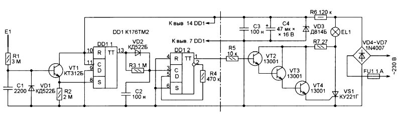
Figure. 1
As a replacement transistor CT 312 b any low power transistor structure of n-p-n, for example, the CT series 312, 315, CT CT 3102.
Теперь о силовой части этого варианта выключателя (на рис. 1 справа от штрихпунктирной линии). Как было упомянуто выше, управляющий ток, необходимый для открывания тринистора КУ221Г, может достигать 130…150 мА. Но в рассматриваемом случае он течёт через коммутируемую лампу EL1, резистор R7 и составной транзистор VT2— VT4 и не нагружает параметрический стабилизатор на стабилитроне VD3, питающий лишь транзистор VT1 и микросхему DD1. Благодаря этому сопротивление резистора может быть довольно большим. Рассеиваемая им мощность не превышает 0,5 Вт.
Compound transistor used to control trinistorom, due to the fact that high-voltage transistors are current transfer ratio 13001 base of no more than 40. Use three transistors is not perestra hovka. When the two transistors for a reliable opening trinistora VS1 had downsize Pres ing resistor R5 to 1 kΩ. It is not only produced in the trigger output, but also required the decrease the resistance of the resistor R6 to 62 com and increase its power to 1 Watt.
In the next version of the switch has been amended, the necessary funds were to be used in it micro scheme to 176 Tm1, and its power would be part of la is built on simistore BT134-600. This option scheme is shown in Figure 1. 2.
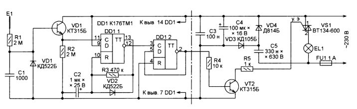
Fig. 2
Here at DD trigger 1.1 assembled single. Therefore, the principle of management of ING switch has become different. On-chip switch described above to 561 Tm2 goes in tivopolozhnoe condition at the time when the sensor kosnovenija E1, further hold finger on it does not play a role. In the version with odnovibratorom when kosnovenie the sensor for the transfer switch to the opposite with standing should be short. If delay finger on the sensor, then after some time, depending on the succinct STI C2 capacitor, single will generate momentum for the next one, however, and so on. Each of these impulses will trigger switch DD 1.2. Consider this deficiency concerned. com cannot be similar to algorithm implementation programme, for example, the chip to 145 AP2. There's a short touch sensors include turning off the lamp and RA, and hold your finger on the sensor leads to decrease or increase the brightness of its light.
It is clear that, in this scenario, you can run kljuchatelja and chip to 176 Tm2 if inputs S it triggers (findings 6 and 8) joined with the General about vodom. Although in this case, the pulses at the output odnovibratora to trigger DD 1.1 have steep drops, without delaying the signal coming from the inverse of the trigger output DD 1.2 at its entrance D, do not succeed. But the necessary delay in this case makes the input capacity of the power part of the switch. That is why rezis Thor R4 connected to inverse (you water 2) rather than direct exit trigger.
This version of the touch part of the switch is the most versatile, since it works as micro scheme to 176 and 176 Tm1 Tm2 and Tm2 561. In the latter case, you can discard the Repeater jemitternogo transistor VT 1.
Now more about the proposed options for the power part. Version with trinistorom, presented at the Fig. 1, described previously. By njatno, that instead you can apply, 221 KU thread any other trinistor with legal permitted voltage in closed position no less than 400 in and let a shock in an open State, not less than the current dial-up load. When applying more stvitelnogo you can trinistora took CHUV switched the resistance of the resistor R7 up to several kΩ. Possible but, in this case, will be able to remove single transistor VT2-VT4.
При монтаже обязательно проверяйте назначение выводов транзисторов 13001, оно бывает различным. Вместо диодов КД522Б можно использовать КД522А или любые другие маломощные кремниевые диоды. Диоды 1N4007 заменяются любыми выпрямительными диодами с обратным напряжением не менее 400 В и допустимым прямым током, не меньшим тока нагрузки. Допускается использовать и выпрямительные мосты с соответствующими параметрами, например, КЦ402 с индексами А—Г, Ж, И, КЦ405 с такими же индексами или импортные мосты 2W10M, BR810, BC207. Вместо стабилитрона Д814Б можно установить любой другой с напряжением стабилизации 7…9 В, например, Д814А или 1N4737А, 1N4787А, 1N4797А.
For powerful load this option isn't exactly convenient, since, in addition to the use of more powerful leg trinistora heatsink, require and more powerful motion rectifiers diodes with heatsinks.
Если планируется управлять только энергосберегающей или светодиодной лампой мощностью не более 15…20 Вт или лампой накаливания мощностью не более 60…75 Вт, можно вообще исключить тринистор, а транзистор VT4 13001 заменить более мощным 13003. При этом теплоотвод не потребуется. Но превышать указанные выше значения мощности нельзя. Во время экспериментов транзистор 13003 мгновенно сгорел от пускового тока лампы накаливания мощностью 150 Вт (около 10 А). Такой же транзистор сгорел при включении энергосберегающей лампы мощностью 30 Вт.
Switch with power option part, depicted in Figure 1. 2, the benefit of giving the application of sensitive TRIAC W 134-600 has the least number of parts and small dimensions. It can be applied and other small shocks triacs opening, for example, BT136-600, BTA06-600, BTA10-600, and others. If you use a TRIAC KU 208 g, then it is advisable to select an instance with the lowest current opening.
При токе открывания более 5…10 мА придётся уменьшать сопротивление резистора R5 в цепи управляющего электрода симистора. А если напряжение питания микросхемы DD1 при открытом симисторе будет падать ниже 3 В, следует увеличить ёмкость конденсатора С5. При этом нельзя забывать и о коэффициенте передачи тока базы транзистора VT2, управляющего симистором. Он не должен быть меньше 150…200.
Diode CD 105 b may be replaced by the same, but with a different word Ying deksom or any rectifier diode with a valid reverse voltage presenting no less than 400 in the rectified current and valid not less than 0.1 a. to replace diodes CD 522 b and d concerning 814 b mentioned above.
This version of the power part you kljuchatelja the most suitable to control the powerful load. So Mu be sure that the TRIAC is calculated on consumed load coy talk, and, if necessary, adjust the TPS enough heatsink close surface scattering.
If you plan to use you kljuchatel for normal incandescent lamp control, better build it power on-chip phase part of vågå to 1182 PM1. It is designed for smooth runs special on and off lamps nakali, as well as adjusting their brightness. Smooth inclusion extends the life of the lamp, and smooth off adds comfort when using fixtures. This option scheme the power part of the switch is represented in Figure 1. 3.

Fig. 3
A detailed description of the phase regulator to 1182 PM1 is available in [3] and [4]. Of course, it may directly control lamp (permissible current-1.2 a), but if it is too powerful, the chip can burn (inrush current incandescent bulb several times more work). Therefore, to enhance reliability in the power option feel good part you added kljuchatelja TRIAC VS1. It can be anything, as long as current management of opening does not exceed 1.2 a. More Than this current, the smaller should be the Pres ing resistor R4, until its deletion.
You can use here and Simi store KU 208 grams and its compilation of the current opening is not obligatory, but you need to reduce the resistance of the resistor R4 tion up to 470 ohms. More on fractional about choosing the TRIAC can be found in [5].
A few words about the resistor R5. For high-power thyristor drivers, including KU, 208, it is not needed. But when the use of imported small thyristor drivers Research Institute shock opening (for example, a series of BT-134) will not be able to do without it-TRIAC will open and when from sutstvii to allow signal. Ve rojatno, chip to 118 PM1 leakage current in a closed position to provide these opening current Wim simisto.
To determine the correct termination resistor R5, the Office must I then it temporarily install change th resistor 1 KOhm. Then connect the findings 6 and 3 micro scheme to 118 PM1 and reduce resistance determination alternating resistor until the lamp turns off EL1. Then measure the AC resistance of the resistor entered and replace it with a constant resistor nearest (downwards).
После подборки резистора R5 необходимо убедиться, что в “разомкнутом” состоянии выключателя симистор полностью закрыт, а напряжение на лампе ЕL1 отсутствует. Дело в том, что при слишком большом сопротивлении резистора R2 на лампу ЕL1 может поступать напряжение, даже когда транзистор VТ1 полностью открыт. Если это напряжение меньше, чем необходимо для свечения лампы, вы даже не будете знать, что в выключенном состоянии ваша настольная лампа потребляет ток, возможно, и не маленький. Для устранения этого дефекта сопротивление резистора R2 необходимо уменьшать.
Нелишне будет измерить напряжение на лампе и при “замкнутом” выключателе. Оно должно быть меньше напряжения в сети не более чем на 2…3 В. Если оно меньше на пять и более вольт, значит, конденсатор С1 имеет большой ток утечки, и его необходимо заменить.
Для существенного увеличения срока службы лампы накаливания нужно выполнить два условия. Во-первых, её включение должно продолжаться не менее 2…3 с. Это время устанавливают подборкой ёмкости конденсатора С1. Чем она больше, тем медленнее включается лампа. Во-вторых, питать лампу нужно напряжением 210…215 В, если это допустимо по условиям освещения. Для ограничения максимального напряжения параллельно конденсатору С1 подключите не показанный на схеме резистор. Его сопротивление, в зависимости от экземпляра микросхемы К1182ПМ1, может лежать в пределах 82…510кОм. Подбирают его экспериментально, глядя на показания подключённого параллельно лампе вольтметра, измеряющего истинное действующее значение переменного напряжения. Её яркость, конечно, немного снизится, но срок службы увеличится значительно. Если вместо этого постоянного резистора применить переменный, получим сенсорный выключатель с регулировкой яркости.
Выключатель с тринистором или симистором может стать источником помех, поэтому необходимо включить последовательно с ним помехоподавляющий дроссель, содержащий пять слоёв обмоточного провода диаметром 0,6…0,7 мм, намотанных виток к витку на ферритовом стержне диаметром 8…10 мм и длиной 25…30 мм.
All the proposed options Sep weedy and parts are interchangeable and switches connect among themselves. The required version can be selected depending on the availability of parts and power load, as well as on the principle of control switches.
Because the device has a technical link with galva network during cutting, observe the taken NALA, all changes can be made only after it has been disconnected from the network. Preferably during forging device feeds it via razvjazy engineered transformer. This sit obezopa and from electric shocks and strikes from damaging details when random circuits on grounded objects.
LITERATURE
- Yerofeyev b. Economy touch light switch. — Radio, 2001, no. 10, pp. 29.30.
- Kutsev m. Touch switch. — Radio, 1999, no. 7. c. 50.
- Gabov c. Automatic lighting control. — Radio, 2003, no. 11, p. 43.
- Nechayev and on-chip power regulators KR 1182 PM1. — Radio. 2000, no. 3, p. 53, 54.
- Nemich a. Chip CD PM1 1182-phase power regulator. — Radio, 1999, no. 7, pp. 44-46; 2000, no. 9, p. 46.
Author: А. КАРПАЧЕВ, г. Железногорск Курской обл.