For realization of the project will need 4 led matrix 8õ8, 4 shear 74HC595 register and managing the microcontroller TINY13A. The aim is to ignite all 256 LEDs from our 8-outlet TINY13A microcontroller. For this case the conclusions on this microcontroller is not enough, this will expand ports shift registers.
Что бы всё работало я написал небольшую “детскую” программку, которая просто дрыгает тремя ногами в нужной нам последовательности.

Figure. 1
No protocols, pure classical dergotnja.
The location of the ports (conclusions) microcontroller TINY13A in the programme the following: port B0 (5) data port B1 (6) synchronization, B2 (7) catch registers, B3 (2) toggle button "statics" movement.
The program itself takes data from the EEPROM and consistently gives their bit shift registers. Since registers are included consistently, then at one time issued to 32 bits. Activates latch registers and we have the led matrix. Then the process is repeated 15 times more and continue around the circle.
The image code is stored in the EEPROM TINY13A microcontroller in order that you could rewrite it yourself and draw your heart desires.
We serve registers first 16 bits data then 16 bits.
We can write the entire row of data and scan together with one line in the EEPROM.
TINY13A controller EEPROM capacity is 64 bytes of 8 bit. And we have 512 bits of memory.
This capacitance just short on data, plus scan 32 bits for 16 rows. But we will do a little bit differently, divide the image and move the scan and the unfolding of the code, there is still a place for this. As a result, we have in place will remain EEPROM for two full frame 16 x 16.
Such reception we get two static pictures. In order to obtain the dynamics or the marquee should be cyclically shift patterns in one direction or another, after each complete frame. As only the first frame will move 16 rows down turn on the second frame.
Frame rate in bits per configuration exhibited 4 Mhz is 16 frames per second. Well, it would be nice to add a static picture mode. For this purpose I did a poll on which controller port 3 hung up button. If the button is broken we creeping line, push the button and the picture stops but the frames on the screen continued to alternate.
While debugging code images that would track the work of each row, you must switch on the incidence of internal 128 kHz generator. To do this, you must set configuration bits as shown below.
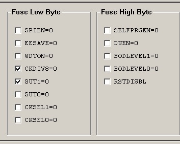
Fig. 2
Another feature of shift registers is as follows. Reading data from memory, we usually read low byte first and immediately served it in registers. As a result of the shift registers our low byte and the Senior Elder is provided which is read by the second, becoming younger. This feature should be taken into account when writing the code for the image. And here there are two: the first is to write code in the same order as he goes into the registers. The second method is to write as it is and then make a permutation of bytes in any programmer or the code editor. I am terribly lazy, take the second way
One important point. As in the matrix we have the LEDs for illumination field matrix must submit to scan 1 and 0 on the data. It is not very comfortable when kodiruesh table images, that I immediately ordered data inversion at output port of the microcontroller TINY13A that would not do it manually.
The second way to create animation on the screen is that we move human-readable address string data in the direction of the second frame. Here plus image that smoothly flows from one frame to another. The second programme in the draft just shows how this action occurs on the screen.
Turn to work with EEPROM.
To edit images in a format 16 x 16 pixels, you can use any graphics editor. It is also possible to do it just on a sheet of paper.
And so we have this construction of screen on which is drawn by a robot.

Fig. 3
Here we see in what direction the move rows and how the data will be written to a string.
Each line in the picture set starting from the bottom up in binary mode, where the led is there 1 where extinguished there 0.
Total turned out 16 rows with data for the first frame:
0000110000011000
0000010000010000
0000010000010000
0001111111111100
0000111111111000
0000011111110000
0001111111111100
0010000111000010
0000000010000000
0001111111111100
0001000010000100
0001011010110100
0001011010110100
0001000010000100
0001111111111100
0000000000000000
Take the Windows calculator and translate each line of data in hex format.
Get:
0C18\0410\0410\1FFC\0FF8\07F0\1FFC\21C2\0080\1FFC\1084\16B4\16B4\1084\1FFC\0000
Then we need to write the data into the table your EEPROM programmer for TINY13A.

Fig. 4
Please note that senior and junior bytes in the table are reversed, as I already wrote above. The two lower lines in the table is the second frame, invent yourself, write there.
Configuration bits for programming exhibited as on the picture below:
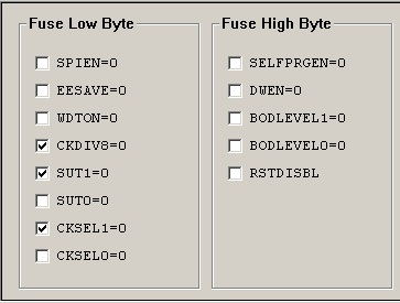
Fig. 5
In the attached archive you will find program scheme and a few pictures in the code.
Video demonstration:
16 x 16 images examples:
- http://pxlshp.com
- http://www.drawbang.com
Author: Novel Twigs. g Solikamsk.