В настоящее время USB является универсальным портом компьютера, к которому подключаются самые разные устройства. На USB выведен достаточно мощный источник напряжения 5V, поэтому многие устройства не только обмениваются данными через него, но и питаются от USB-порта. Это различные сканеры, вебкамеры, выносные CD или DVD-приводы, модемы и др. В интернете можно встретить описания весьма глупых безделушек, питающихся от USB, – микропылесосы, нагреватели чая, и даже микрокофеварки.
In principle, from USB you can feed many more peripherals, even are not designed for this, but there are some that restriction. In particular, on behalf of the voltage supply, which only 5V. When that peripherals, fed from their own network adapters usually requires a higher voltage, and for many devices power supply 5V is not always what you need.
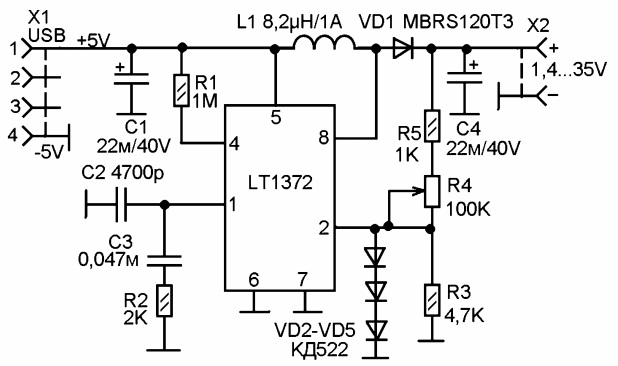
The illustration shows a simple adapter, which lets you get from the USB port stable constant voltage adjustable proposal ranging from 1.4 to 35V, provided that the load current will not exceed 350 Max. By using this adapter, you can feed from the USB port a variety of circuits and devices, and even use it as a laboratory source, what is most relevant when working with USB laboratory, "or affordable selection of programs such as those that allow a PC with sound card turn in low frequency oscilloscope PF Millivolt meter, generator, frequency counter (such programs are typically available online for free).
The scheme is built on the LT1372 IC designed to build circuits DC-DC voltage converters. Built-in generator produces pulses of around 500 kHz. Stabilization scheme regulates the breadth of these impulses and delivers them at the exit key on the output transistor, which is part of the chip. In chip transistor output is protection from excess current through it. When the current through it more than 1.3 and triggered the protection. Protection is built on the principle of voltage measurement current measurement provisions of the resistance in the circuit the emitter of the output transistor. Measuring resistance is part of micro circuitry.
To the collector of the output transistor is connected inductance L1 is "pumping" change leg strain. Then vyprjam was led Here and smoothed con densatorom C4. Output voltage regulation is made by treason tion latitude impulses originating at the base of the output transistor. Proximity sensor for the measurement of the output voltage is the comparator. The output voltage should be 1 2, 25V, this output voltage is supplied from the output of the schema through the divider resistors. And kompa Rathor regulates the breadth of impulses so that the output 2 was exactly 1, 25V. Thus, by adjusting the voltage divider can be regulated output voltage. With the specified diagram resistances of resistors R3-R5 can be precisely adjusting the output voltage from 1.4 to 35V.
Because a block intended to be generic, with the possibility of a rapid output tension adjustment Opera, in the schema between the 2 and total output minus included three diode VD2-VD5. Their task is to limit the voltage at pin 2 to not display chip failure when the knob shaft R4 in the direction of reducing the output voltage.
When the output current to 0.35 A heatsink is not required.
Author: A. Zhurbin