Блоки управления шаговыми двигателями обычно содержат несколько логических микросхем или микроконтроллер. Однако в тех случаях, когда сложный закон управления двигателем не требуется, а достаточно лишь вращать его вал в одну или другую сторону, отсчитывая число шагов “на глаз”, от сложной логики можно отказаться.
For manual control of stepper motor opening and closing the greenhouse, I applied valkoder. But not the usual, with two groups of contacts, closing and razmykajushhihsja with shift on half and specially manufactured, with four (by number of winding engine) Group of alternating turns contacts are closed with a moving contact when rotating the shaft on which a novelised version of the sliding contact. Fixed valkodera contacts are connected to the motor windings through electronic keys, switching the windings.
Design homemade valkodera is shown in Figure 1. 1. The ring 4 of insulating material is wound coil 3, containing 28 turns four clasped together lacquered odnozhilnymi copper wires. Sizes 4 rings and the diameter of the wires must be chosen so that the inner surface of the ring coils tightly, almost without gaps, formed in one layer, and wires alternated in order 1-2-3-4 without perehljostov.
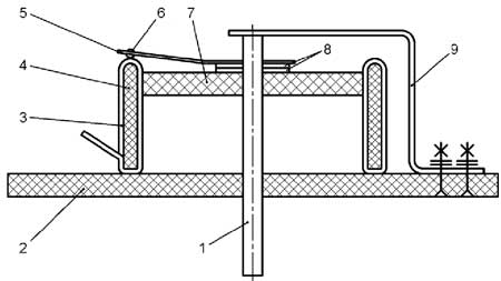
Figure. 1
The upper zakrugljonnomu shear rings 4 wires must be, if possible, tighter clearances between them fill in with epoxy. Inside 4 rings tightly inserted carved from sheet insulating material 7 simmering with a hole for the brass shaft 1. Washer 7 also krepjat epoxy. The same hole, as in a washer 7, drill in under 2.
After hardening of the resin ring with 4 winding put upper face onto a sheet laid on a smooth surface a fine-grained sandpaper and evenly soshlifovyvajut wire-contacts and epoxy jumper between them approximately one quarter of the diameter wires. So create a surface on which to slide a steel ball rolling contact 6 5. Parastal-copper provides reliable contact and easy gliding.
Elastic sliding contact 5 with a hole for the ball 6 solder closer to the upper end of the shaft 1. At the lower end of the shaft 1 put two metal washers 8 and pass through a hole in a shaft washer 7, then through the ring with 4 winding (contact surface rotated upward) and finally through the hole drilled in the base 2.
Selecting the optimum position on the basis of 4 rings 2, sought to shaft 1 easily rotated, and the ball slid 6 strictly on ogoljonnoj surface contacts, clinging to it. In this position the ring 4 lock based on 2 epoxy resin. Remains only to fix the axial displacement of the shaft 1, pushing his bracket 9. Turned out valkoder at 112 positions (fig. 2).

Fig. 2
It will in turn connect to a power source winding unipolar stepper motor, which per revolution of the shaft will be valkodera do 112 steps. The direction of the steps will be the same as the unit on the shaft valkodera control knobs, and their frequency will be determined by the speed of its rotation.
In Figure 1. 3 shows a schematic diagram of the control unit unipolar stepper motor M1 using described valkodera, it is marked S1. Since the block four identical electronic key, consider only one of them collected on transistor VT1 and VT2.

Fig. 3
Suppose that when the sliding contact power supply valkodera is not connected with any of the stationary Contacts group a. So the transistor V71 opened and discharged capacitor C1. Transistor VT2 closed, current through it in the chain of his runoff flows M1 motor winding. HL1 led extinguished.
At connection time rolling contact with a stationary contact group and transistor VT1 closes. Capacitor C2 starts charging through resistors R3 and R4. Caused by the current charging voltage drop on resistor R4 opens a field-effect transistor UT2 and keeps it open. Through the winding of the motor current, flows and led HL1 included to indicate this. But when the capacitor C2 is charged to such an extent that the voltage at the resistor R4 will fall below the threshold of opening the transistor VT2, it closes. This restricts the pulse duration of the current in the winding, which is necessary in cases where the handle valkodera long time doesn't rotate or doing it too slowly.
Keep in mind that the absence of a current in the motor windings in pauses between steps saves electricity and reduces engine heat and transistors in the electronic keys, but weakens its fixation the rotor in static positions. It doesn't really matter if reliable fixing of the engine rotor in position is not required or, for example, where the torque is transferred to the relocatable object via a worm gear.
When disconnecting the mobile and stationary contacts transistor W1 opens. Through it, and discharges the capacitor C2 VD1 diode. If the transistor VT2 was open, it closes and stops the motor winding current and the led goes out. HL1
VD2 diode is designed to suppress self-induction voltage pulses that occur on winding in moments of ending the current through it current. A filter is required to prevent the self-excitation R1d device. It is possible, because valkoder consists essentially of four inductance coils connected inductively, as well as through inter-turn capacity.
Резисторы R21-R24 ограничивают ток в обмотках двигателя. Их сопротивление придётся подбирать индивидуально для двигателя каждого типа. Возможно, они совсем не потребуются. Светодиоды HL1-HL4 рекомендуется разместить так, чтобы создаваемый ими “бегущий огонь”, перемещаясь, показывал направление вращения ротора шагового двигателя. При несовпадении этих направлений или пропуске шагов нужно проверить порядок подключения обмоток двигателя к выходам электронных ключей.
I have tested this device with stepper motors PM42L-EPAO and 103-550-0149 and got good results.
Diagram of control bipolar stepper motor harder reviewed as required not only switch winding, but also change the direction of current through them current. She is depicted in Figure 1. 4. Input chain (A)-(E) can be connected to both outputs of the same electronic key device collected under the scheme fig. 3, and directly to the same contact groups valkodera. However, in the latter case will not limit the duration of impulses in the motor windings.
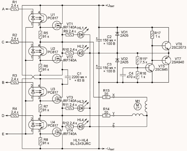
Fig. 4
The General conclusion in the present case, the motor winding is connected to an artificial midpoint voltage supply voltage created by the site on a transistor VT5-VT7. This reduced twice served on the motor windings the voltage, but saved from having to apply additional electronic keys for switching the second conclusions of each winding. Voltage at a point Z is equal to half the U ^ set selection of resistors R15. Please be aware that changing the supply voltage of the resistor will have to repeat the selection.
From the node to the transistor VT5-VT7 can be waived if you apply for the engine power bipolar source with real high point, which should be connected to a chain of Z.
The device was tested with engines-16PU M002-G1 and M49SP-1. It turned out that in continuous operation and current, 5V engine more than 0.2 and all powerful transistors must be installed on a heat sink.
In amateur conditions passport data on used stepper motors are usually absent. No appointment data and their findings, the number of which happens to be different. I usually walk out of predicament as follows.
Прежде всего, с помощью омметра нахожу выводы каждой из обмоток. Если их две (с общим выводом или без него) – двигатель биполярный. При отсутствии общего вывода создаю его, соединив вместе по одному (любому) выводу каждой обмотки. Чтобы безошибочно оценивать на глаз направление шагов вала двигателя, надеваю на него указатель в виде стрелки. Затем, поочерёдно подключая к общему и к свободному выводу каждой обмотки источник питания в разной полярности, нахожу такую последовательность подключений, при которой вал двигателя без пропусков и сбоев “шагает” в нужном направлении.
Приблизительно такую же процедуру я использую с униполярным двигателем. Он может иметь четыре обмотки с общим пятым выводом или две пары обмоток с отдельным общим выводом каждая (всего шесть выводов). В последнем случае общие провода пар я объединяю в один. Подключая источник питания плюсом к общему проводу всех обмоток, а минусом – поочерёдно к каждой обмотке, определяю их последовательность для шагов в нужном направлении.
Самый сложный случай – двигатель с четырьмя обмотками, имеющими восемь отдельных выводов. Эти обмотки можно соединять по-разному, делая двигатель униполярным или биполярным. Но на поиск правильной последовательности подачи на них напряжения придётся затратить гораздо больше времени, чем в предыдущих случаях.
Author: C. Dolganov, g. Barabinsk Novosibirsk oblast.