In heating systems for private homes (cottages) using gas or electric boilers, pressure drops from time to time, causing coolant heating have to shut down to search for and eliminate the cause of the failure. It can be mikroprotechka the coolant through the piping connections and faucets, automatic reset boiler air accumulated in the system, the system allows the winter as a result of power outages, etc.
The proposed device allows you to monitor the pressure of the coolant and restore it in the fall. Especially clearly evident coolant pressure fluctuations, if the gas boiler is equipped with managing them air temperature sensor in the House. As soon as the temperature reaches the set value, such a boiler gets a command to extinguish the burner heat cools down (especially in severe winter frosts), its pressure drops sometimes to a critical level. After that, gas boiler does not automatically engage and displays a message about the refusal.
When people are always in the House, the problem is solved simply: in the heating system, you can always add water from the water system. But if a country house visit only on weekends and discover that it has cooled down, and heating system does not launch automatically, you have to spend several hours on troubleshooting running boiler and heating homes.
Pressure fluctuations become inevitable and are critical in cases where, for example, the temperature in the room during the weekend maintained at +23° c, and during the week is not above +10° c. It's bad for construction and finishing materials, and strong cold defrost water systems may occur.
The device at the time responding to possible leaks. If there is a serious decompression system and pressure could not be restored for two minutes, the regulator cuts off the water, so as not to flood the House and includes an alarm signal. If leakage is negligible but more conventional mikropoter, and within a week was able to recover twice the pressure that nevertheless again fell below normal, the third time water supply will be blocked. To fix this problem will be a blinking alarm signal. From this State, you can display the regulator, only disabling it is not less than 5 hundred outlet and turning on again.
In case of pressure drop is to turn off the boiler and re-enable it once pressure is restored. It is necessary to set the initial state of the boiler controller.
With the right execution and adjustment of heating system pressure coolant in it have to recover no more than one to three times per heating season.
Схема регулятора изображена на рис. 1. Он построен на микроконтроллере PIC12F629-I/P (DD1). Загруженная в микроконтроллер программа непрерывно контролирует давление теплоносителя. Датчик давления (рис. 2) сделан из обычного стрелочного манометра, к стрелке которого приклеен эпоксидным клеем полукруглый “флажок” из фольги, перекрывающий поток инфракрасных лучей между излучающим диодом VD1 и фототранзистором VT2, если давление понижено. В этом случае фототранзистор закрыт, а напряжение на его коллекторе и на входе GP3 микроконтроллера имеет высокий логический уровень.
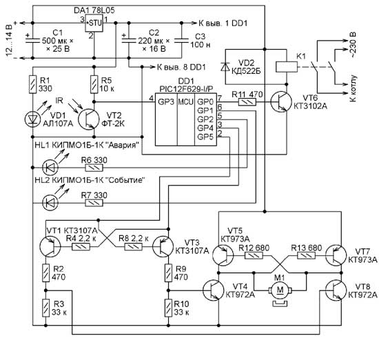
Figure. 1
Когда давление достигает нормы или превышает её, “флажок” выходит из зазора между излучающим диодом и фототранзистором, который под действием ИК-излучения открывается. Уровень напряжения на коллекторе фототранзистора и на входе GP3 микроконтроллера становится низким.
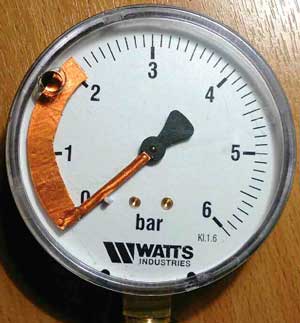
Fig. 2
Analyzing the input voltage level GP3, program the microcontroller decides whether to open or close the faucet supplying the heating system heat carrier (water water). The motor M1, depending on the polarity of the voltage annexed thereto, turns toward the faucet opening or closing.
Применённый кран CWX-15N CR-01 (рис. 3) – латунный шаровой с электроприводом и конечными выключателями в крайних положениях. Для его открывания напряжение на электродвигатель программа подаёт в течение 3 с. Для гарантированного закрывания крана напряжение соответствующей полярности подаётся дольше – 7 с.

Fig. 3
Management of motor M1 is built on transistor VT1, VT3-VT5, and VT7 VT8. When walkouts and GP4 GP5 microcontroller mounted low logic voltage levels, all of these transistors are closed, so the motor M1 is dead.
Одновременное появление на выходах GP4 и GP5 высоких логических уровней напряжения программой не предусмотрено. Однако если это всё-таки произойдёт в результате сбоя, транзисторы VT1 и VT3 останутся закрытыми, предохраняя этим от одновременного открывания транзисторы VT4, VT5, VT7 и VT8, которые иначе могли бы быть повреждены текущим через них “сквозным” током.
Different levels of voltage placed on its outputs GP4 and GP5 opened only one transistor VT1 or VT3. When it opened, respectively, pairs of transistors VT4 VT5 and either VT7 VT8 and by connecting the motor M1 voltage source in one or the other polarity. The tap is opened or closed in accordance with the command of the microcontroller.
Если при открытом кране в течение двух минут давление не придёт в норму, он будет закрыт, чтобы не затопить помещение, и будет включён светодиод HL1 “Авария”. Попыток восстановить давление больше не будет до устранения поломки и установки микроконтроллера DD1 в исходное состояние путём отключения питания устройства на 5 с.
With little pressure leakage can be restored, but if it falls again, because the leakage persists, the device will try to restore the pressure again. However, for the third time, he will not open the faucet, and the led will be flashing HL1. Attempts to restore the pressure will no longer be able to eliminate breakage and bring the microcontroller to its original state.
Если регулятор хотя бы однажды восстанавливал давление, будет включён светодиод HL2 “Событие”, сигнализируя об этом. Заметив этот сигнал, рекомендуется обнулить счётчик событий, установив микроконтроллер в исходное состояние.
To automatically restart the boiler controller should be connected to the mains through the relay contacts K1. At a reduced pressure of the coolant it is turned off and turned on again through 3 with pressure after the restore. This relay can be of any type, designed for switching mains voltage with two pairs of normally open contacts and winding with nominal voltage of 12 v and resistance at least 150 ohms. For boiler with electric heaters K1 should have contacts with sufficient capacity.
Author: A. Femme, Ryazan
При падении давления котёл отключается сам. Любой котёл контролирует наличие давления в системе отопления (но не восстанавливает его). Данное устройство восстанавливает давление. Если зимой свет отключат на 3 – 4 часа система остывает трудно предсказать насколько упадёт давление.