The reason for the design and manufacture of the proposed device was the desire to replace a galvanic element power supply wall electromechanical clock battery. Available charger charge allowed only an even number of batteries, and had to be recharged one Ni-MH battery, size AA.
При просмотре литературы заинтересовало “Автоматическое зарядное устройство аккумуляторной батареи”, описанное Н. Скриндевским в “Радио”, 1991, № 12, с. 28-30. Понравилась заложенная в эту конструкцию идея заряжать аккумулятор циклически, чередуя интервалы зарядки с интервалами измерения ЭДС аккумулятора. В результате макетирования и отладки получилось предлагаемое зарядное устройство.
Main technical characteristics
Напряжение питания, В ………… 5
Ток зарядки, мА ……………..150
Порог отключения тока зарядки, В…………………1,38
Порог включения тока зарядки, В …………………….. 1
Длительность цикла зарядки, с……………………..40
Длительность измерения, с………1
A diagram of this device is shown in Figure 1. 1. On the transistor VT2, resistors R9-R12 and led HL1 assembled current source. Manages transistor VT1. HL1 led has two functions: serves as a source of stable voltage coming to the base transistor VT2 through the resistor R10, and at the same time the battery indicator. Resistors R11 and R12 specify charging current whose value in milliamps chosen numerically equal to the nominal battery capacity G1 in milliamp-hours. Resistor R9 limits the current through the led HL1. VD2 diode prevents battery discharge the G1 through the charger if you disconnect power supply or a power outage.
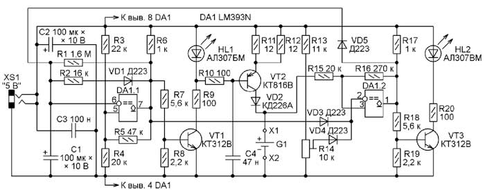
Figure. 1
The voltage comparator DA 1.1, resistors R1-R6, the capacitor C1 and the diode VD1 assembled 40 duration pulse sequence generator with 1 with a pause in between pulses are measured EMF of the battery.
На время измерения источник тока отключается от заряжаемого аккумулятора. В это время происходит сравнение напряжения на аккумуляторе с образцовым – тем, до которого необходимо зарядить аккумулятор. Диод VD4 препятствует попаданию блокирующего напряжения на движок подстроечного резистора R14.
The voltage comparator DA 1.2 and resistors R13-R17 assembled Schmitt trigger that monitors the voltage on the battery zarjazhaemom. For proper operation of the trigger on the inverting input of the comparator, the comparator output 1.2 with DA DA 1.1 while charging through the diode enters VD3 blocking voltage.
On reaching the voltage on the battery specified trimpot R14 and applied to the comparator input DA invertirujushhumu 1.2, the last high-level voltage appears, which through the diode VD5 arrives at the inverting input comparator DA1. 1, blocking the work of the generator. At the output of the comparator DA 1.1 installed low voltage transistor VT1 closes led extinguishes. HL1
Одновременно напряжение высокого уровня с выхода компаратора DA1.2 поступает и на базу транзистора VT3, открывая его, светодиод HL2 включается, сигнализируя о завершении зарядки аккумулятора. Образцовое напряжение на инвертирующем входе компаратора DA1.2 выбрано равным 1,38 В – таким же, как у имеющегося в наличии зарядного устройства промышленного изготовления.
Микросхему LM393N можно заменить на К1401СА3А или другую из многих её аналогов, а транзисторы КТ312В – на аналогичные с другими буквенными индексами или на транзисторы серии КТ315. Заменой транзистора КТ816В может служить КТ814В. Вместо диодов Д223 подойдут Д220 или серии КД522, а вместо КД226А – любой выпрямительный диод с допустимым прямым током не менее 200 мА. При замене светодиодов серии АЛ307 на более современные рекомендуется увеличить номиналы резисторов R9 и R20, чтобы уменьшить до приемлемого уровня яркость их свечения.
Оксидные конденсаторы С1, С2 – импортные или отечественные серий К50-16, К50-35. Конденсаторы С3 и С4 – любые керамические или плёночные. Подстроечный резистор R14 – импортный. Постоянные резисторы – МЛТ-0,125 или аналогичные.
Charger are gathered in a small case of dental handpiece. With the lid open, it is shown in the figure. 2. Originally planned to arrange the battery holder (pins X 1 and X 2) directly on the printed circuit board, and the Board developed under this location. In a subsequent holder was pasted in the chassis cover.

Fig. 2
Чертёж печатной платы зарядного устройства изображён на рис. 3. Для микросхемы LM393N на ней установлена панель. Постоянные резисторы установлены как параллельно, так и перпендикулярно поверхности платы. Один из выводов резистора R2 и вывод
the cathode of the diode VD1 decorating fee and the remaining free conclusions of these elements are connected above it. Pasted in the battery holder cover and LEDs are connected with flexible insulated mounting wires.

Fig. 3
In a correctly assembled device should only adjust the charging current and battery shutdown voltage charging. Before installing the charging current chip DA1 to extract from the Panel, and to contacts instead of x 1 and x 2 battery connect 33 Ohm resistor or miniature incandescent lamp MN 6.3 -0.3 through the multimeter in DC measurement mode the limit of not less than 200 Ma. Compilation of resistor R11, R12 should set the multimeter readings equal to 150 Ma. But you can install and the other charging current, depending on the battery capacity.
Disconnect the battery charging voltage regulation is limited to installing the trimpot R14 1.38 in voltage between 2 and 4 Panel Pocket comparator. Then disconnect the device from the power source and insert a chip into the Panel. The charger is now ready for use.
The width of the hysteresis loop of the comparator trigger on DA 1.2 depends on the resistance of resistors R15 and R16. Decrease the resistance of the resistors R15 increases the voltage activating the trigger.
Author: G. Kosolapov, Kirovo-Chepetsk, Kirov region.