The proposed simple adjustable stabilizer in a wide range of output voltage and current protection can be used in both single-and mnogoka national laboratory power supplies.
Выходное напряжение стабилизатора можно регулировать от 3 до 27 В, Наибольший ток нагрузки — 3А. Его прототипом послужил стабилизатор, описанный в статье А. Уварова “Лабораторный источник питания” (“Радиоконструктор”, 2001, № 10, с. 18—20). Самое полезное, что я увидел в этой конструкции, — не требующий отдельной обмотки трансформатора способ питания маломощных узлов стабилизатора. От оптрона в узле токовой защиты я отказался и сделал эту защиту регулируемой.
The regulator circuit shown in Fig. 1. Stabilizer — compensation type with continuous regulation of the regulating element composite transistor VT4VT5. The reference voltage generates a parametric stabilizer resistor R11 and the Zener diode VD2. Part of the snimae with engine AC resistor R12, OU DA4 compares with part of the original voltage stabilizer you removed with a divisor of resistors R17 and R18. Enhanced OU signal glasovanija Rasso manages composite Tran zistorom, supporting output to prjazhenie to the specified that regulate a variable resistor R12.
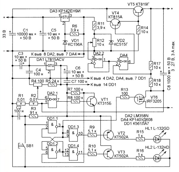
Figure. 1
Маломощные узлы стабилизатора питаются от интегрального стабилизатора DA3. Включенный последовательно с его общим выводом стабилитрон VD1 поднимает выходное напряжение стабилизатора VD3 до 29…30 В. Интегральный стабилизатор DA1 предназначен для питания узла токовой защиты.
When feeding to the stabilizer input voltage R3C2 circuit generates a pulse that sets the trigger on the elements DD1.1 and DD1.2 in a state in which a field-effect transistor VT6 is open, whereby the load connected to the output of the stabilizer included this is indicated by a green led HL1. OU DA2.1 compares the signal from the current sensor (resistors R1 and R2) and a threshold voltage taken from the engine of the variable resistor 134. If the threshold is exceeded will be opened connected to the output of op-amp the transistor VT1. Voltage low logic level with its collector goes to pin 6 of the element DD1.2 and moves the trigger in a state in which a field-effect transistor VT6 will be closed, which will disconnect the load from the output of the stabilizer at the same time will turn off the led HL1 and turns on the red led НL2, signaling the excess variable resistor R4 allowable output current of the stabilizer.
After eliminating the cause of the overload by pressing the button BB1 is possible to return the trigger to its original state and once again be connected to the stabilizer load. Note that when the stabilizer the protection is triggered from the charging current of the capacitor C8. On reflection, I did not modify this node, preserving the peculiar indication of his health.

Fig. 2
The stabilizer is assembled mostly on the PCB size 97x82x1,5 mm, the drawing of the printed conductors is given by Figure. 2and the arrangement of elements on Fig. 3. The capacitor C1, the led НL1 and НL2 variable resistors R4 and R12, SB1 and transistor VT5 are outside of the Board. Heat sink transistor VТ5 — cooler DEEPCOOL CK-AM209 fan 12 V processor AMD.
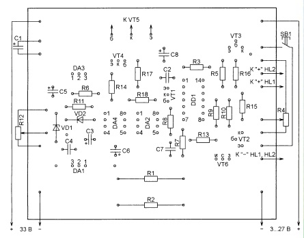
Fig. 3
Конденсатор С1 служит сглаживающим для выпрямителя, от которого питают стабилизатор, и составлен из пяти соединенных параллельно конденсаторов К50-16 ёмкостью 2000 мкФ. Эти конденсаторы выпуска 1989 г. пришлось формовать в течение десяти часов, постепенно повышая приложенное к ним напряжение до номинальных 50 В. Разумеется, предпочтительней применить в качестве С1 современные оксидные конденсаторы ёмкостью 2000 – 10000 мкФ с номинальным напряжением не ниже 50 В.
Manufacturing cost of the better foil-clad material with a thickness of copper coating is not less than 70 microns, but in a pinch you can use and more common material coated with a thickness of 35 µm. The Nye print conductors circuits should be along the entire length of napajat top copper wire diameter not less than 1 mm.
Resistors R1 and R2 are RX27-1 (SQE) power 5 Watts. the other is the CF-50 resistors regain its lost (1-4). Re-art resistor R2 must have the linear dependence of resistance on the rotation axis of the engine. As R4 applied wire variable resistor PCB-1A but his replacement neprovolochnym.
CT 502 transistors and can apply for any of the CT series 3107 and CT 315 CT series of b-3102. It should draw attention to the differences in how conclusions Replacement Tran zistora CT and CT-815 969 or CT 503 d, it is tested in practice. Replace Tran zistora CT 819 g must be chosen with the permitted legal collector-emitter voltage emic ter over 40 in and maximum constant current permanent collector at least 5 a. Its allowable power dissipation (heat sink) must be not less than 100 Watts. Field-effect transistor IRF3205 to replace the n other indulges Cana scrap. with the least possible with resistance in the open position, and with the threshold voltage of not more than 4 b. Suitable, for example, IRL2505.
Analogue integral stabilizer CD 142 EN9I — import 7824. But can but apply and stabilizer LM317T, which should reduce the nominal value of the resistor R6 to 240 Ohm and Zener diode VD1 replace resistor 5.6 kohm dissipated resistance. Instead of Zener diodes are suitable for domestic import power 0.5 Watt with the appropriate voltage stabilization.
Для замены микросхем LM358N и КР140УД608 желательно выбирать ОУ класса “rail-to-rail”. В первом случае это необходимо для успешной работы токовой защиты, а во втором позволит уменьшить практически до нуля минимальное выходное напряжение стабилизатора Микросхему К561ЛА7 можно заменить импортной CD4011B. Немаловажно, чтобы назначение и расположение выводов микросхем, выбранных в качестве замен, было бы таким же, как у заменяемых. Это позволит не переделывать печатную плату.
When a serviceable parts and correct Mr. stabilizer installation requires a minimum of forging. You should check the presence of voltage at the outputs of the integrated stabilizers DA1 and DA3 and core stabilizer. Then make regular output voltage regulation of variable resistor R12. You'll probably want to pick up the resistance of the resistor R17 to upper end (diagram) engine change leg resistor R12 corresponded to 27 output voltage at you with this operation to be sure regulator output connect the load impedance 100 Ohm 300 ....
The next operation is to check the work of current protection. To the exit STA bilizatora connect a load resistor of about 10 ohms. I IP polzoval four resistor resistance 10 Ohms and power was 10 Watts each person connected by series-parallel. Resistor R4 engine set all the way to the right (on) position. When smooth increase of output voltage current protection regulator should work, when this led instead to be inducted NL2 led HL1. If the current CPA batyvanija protection more (less) required should be increased (they sew) resistance of the resistor R5.
Host protection depends on the resistance of resistors R1 and R2. If in a small trigger current is not necessary, one of the resistors can be removed by replacing it provoloch Noah jumper. In manufactured 100 bilizatorah with two resistors minimum tripping current protection you turned out to be equal to 0.16 and Maxi — white, 3.2 a.
Final steps — manufacture of manufacture and grading scale for AC resistor R4 perform using load rezis Tori and ammeter.
To create a full range of transformer supply needs to be supplemented by stabilizer Bloch lowering transformer and rectifier.
Applying a transformer with several Kimi secondary windings and collecting the required number of described stabilizato ditch, can produce multichannel power source with multiple totally untied and independent adjustable output prjazhenijami at Simo.
In the author's version used a transformer TS 180-2, which removed all secondary windings are wound four instead of winding wire coils 50 PEV-2 diamet rum 1.3 mm (two on each core magnetic core). After assembling each transformer winding od leg cores connected follower but with one of the windings of the second core. As a result, received two windings with NUM scrap turns 100 and 32 voltage are connected in rectifier diode bridges Nye on talk and 5 c to pustimym reverse voltage of 100 v.
Power supply enclosure finished, with the standing of the two u-shaped pieces. Its size is 270x200x95 mm. Two identical cooler refrigerated them transistors are mounted on the rear of the chassis. Engines their fans connected sequence ably and connected to one of the rectifier through limiting current of resistor. Not shown in the diagram with a voltmeter analog measurement in 30 connected to you move each stabilizer, size against the front wall of the chassis. There are also controls, LEDs and connection clamps tion load.
Author: N. SALIMOV, Revda, Sverdlovsk region.
Source: Radio No. 5/2017