The quality of our electricity grids, to put it mildly, leaves much to be desired. So many others are constantly looking for ways of protecting tives of household appliances.
On the pages of the magazine "Radioamateur" multiple schema published pointed protective mouth starters. Suggest another option for a simple block protection in the form of push-button extension Office. The main difference from similar devices [1] is the only one common power supply of meritelnoj and Executive parts diagram. Measuring cascade made in cadaver Tomb storah VT1-VT3 (fig. 1), monitors the voltage at the load rectifier R5, HL1, U1, which depends on mains voltage.
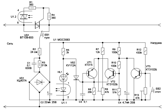
Figure. 1
Transistors-VT1 VT3 work in mikrotokovom mode and little load rectifier.
Unlike other protective devices application optosimistora MOE 3063 with shock treatment included 5 Ma simplified administration and reduced the capacity of the TRIAC of the capacitor C1. Also changed the connection start button, Che Rez it passes only supply current management schemes. All this has increased the economic michnost and reduced dimensions. Performance designs, but were not imitations of breakage of zero wires (230 voltage to the device in and then Rez some increase to 400) incandescent lamp, included as a load, not peregorala.
В авторском варианте максимальный порог срабатывания 260 В, минимальный – 170 В. Верхний уровень выбран из-за местных условий — в ночные часы напряжение может доходить до 255 В.
The device works as follows: after pressing the Start button the voltage across R2, C1, diode bridge enters onto the diagram. Optocoupler U1 includes a TRIAC, and the load is connected to the network.
When you release the button, the scheme remains switched on, since I have a breakthrough through the voltage gets outdoor TRIAC VS1 until the supply voltage is in watch ing. If the voltage at engine Resi Stora R8 exceeds the prescribed level, from transistor VT1 lies included in mikromoshhnogo concerning mode. When this opens the Xia thyristor VS2 and zashuntiruet optocoupler U1 power and TRIAC obestochit and load protection device.
Voltage deviation on delitele R12R13 below the limit will cause a closing impulse output Tora VT3. This starts the charging condensation Tora delays C4, it is designed to prevent rotation of the positives in the short-term failures and voltage when turning on the device. When the voltage on C4 will reach threshold from kryvanija, transistor VT2 includes thyristor VS2 are optocoupler U1 and TRIAC VS1.
Similarly, the device works and when the MOUS tii "stop" button. In this case, RA is being tested botosposobnost schema.
The design and details
Большая часть деталей расположена на печатной плате размерами 43×29 мм. Диодный мост КЦ407А смонтирован вертикально – его выводы переменного напряжения изогнуты на 90°, и к ним припаяны провода.
Так как блок защиты предполагалось использовать с небольшой нагрузкой (телевизор, DVD, тюнер СТВ), симистор расположен на небольшом теплоотводе — алюминиевой пластине 50×25 мм. При большей мощности соответственно увеличить размеры теплоотвода. Устройство выполнено в корпусе пятиместного удлинителя, три розетки оставлены, а на месте двух расположена схема.
Optosymistor МОС3063 replaced МОС3083. You can also try to apply МОС3062, МОС3082, but since the current operation they have more, you may need to increase the value of C1 and C2.
In place of the thyristor MCR100 КУ112А works well.
Транзистор КТ315 с любым буквенным индексом, должен обеспечивать напряжение стабилизации 7…8 В, а КТ3102Б можно заменить КТ3102В.
Any suitable triac current with acceptable voltage below 600 V. the Tested device BT134-600, TC2-25.
As buttons SB1, SB2 are used microswitches MP-1, MP-3 (instead of SB2 you can also apply a miniature button from the electronic apparatus, for example IPP-159).
Indicator HL1-any bright SWE todiod.
Diode bridge can be replaced, DF04 or similar DB104.
Capacitor C1 type to 73-17, to 78-2 with a maxi of voltage not below in 630.
Configuring
Before configuring a resistor R8 engines and R13 must be set to the lower position and under the scheme include to the network via an autotransformer. Click the Start button, the tanned Xia led HL1 and it is necessary to measure the voltage on the capacitor C2, it depends on the variability it bone C1 and can range from 12 to 16 in, with mains voltages of 230 v.
Then expose the autotransformer is the maximum input voltage for Rog activation (260), and shifting up to 138 bivaemsja off the TRIAC.
Install using the avtotransforma Tora minimum input voltage fires at Bani 170 in and slowly rotate R13 to disconnect ensuring the TRIAC.
Available in the presence of autotransformer TI PA ARB 250 not lowering voltage below 200 in, so to get less stress, had to turn it the other way around: the network connection to enable its exit and load-to the entrance. Finally advancing again check the stability of the otkljuche in the upper and lower levels and reliability of the TRIAC in the operating range.
The main drawback of the design is the following: If you click "start" at high or low voltage will occur first and then switch the load off. Preferably, of course, to the inclusion of prjazhenii disaster from happening at all. But this shortcoming is typical of almost all such devices, described in Google re, to an even greater extent. In the known device consumed voltage will flow to the load all the time until the Start button is pressed because it enabled the Executive contacts in parallel leg of the relay.
The design has no galvanic razvjaz Ki with the supply network 230 v/50 Hz, so when you configure must follow the rules of safety jelektrobe.
Literature
- Шрайбер А. Устройство защиты от перепадов напряжения в электросети // Радио. – 2001. – №2. – С.46.
Author: Vladimir Shishkin, Verkhnyaya Tura, Sverdlovsk region.
Source: Radioamator No. 4/2017