1956 in the United States published an article [1], which first described the SCR is a four layer semiconductor device with controllable S-shaped current-voltage characteristic. Its graphical image and the equivalent circuit shown in Figure. 1. Since then, the range of SCR and triac structures has greatly expanded, but the result of natural selection preferential distribution of the received SCRs classic structure. Along with indisputable advantages, the SCRs revealed and disadvantages: low input resistance, poor frequency properties, a significant voltage drop across the open device, etc.

Figure. 1
The problem of low input resistance was solved by the creation in 1981 -1984. SCR, which is a combination of field, including insulated gate transistor, and the normal SCR [2, 3]. Equivalent circuits of some of these devices is shown in Figure. 2.

Fig. 2
Below are a few schemes trinitrotoluene structures built using field-effect transistors with insulated gate. Not all of them are perfect, but further improvement can serve as the basis for the creation of the SCR, which has improved properties.
On Fig. 3 shows an example of analog SCR key element structure of the CMOS control circuit. His faults — low voltage (15 V), and a significant voltage drop in the open state (up to 3). Advantages — high input impedance (about 1 MOhm), improved performance. To further reduce the voltage drop in the open state can be used modern modification of the CMOS chip, capable of operating at voltage less than 3 V.

Fig. 3
On Figure. 4 изображён аналог тринистора на двух полевых транзисторах с разными типами проводимости каналов. Он отличается тем, что имеет два управляющих электрода. Для его открывания управляющий электрод УЭ1 достаточно на мгновение соединить с катодом либо на управляющий электрод УЭ2 кратковременно подать напряжение выше 4,1 В. Для закрывания достаточно, как обычно, на мгновение разорвать цепь анода либо подать на управляющий электрод УЭ2 напряжение ниже 4 В (0…4В), в том числе просто соединив УЭ2 с катодом. Падение напряжения между анодом и катодом этого аналога тринистора в открытом состоянии — около 5 В при токе анода 10 мА. При закрытом тринисторе и напряжении анод-катод 12 В ток не превышает 12 мкА.

Fig. 4
The analogue of the SCR, the scheme of which is depicted in Figure. 5, также выполнен на двух полевых транзисторах с изолированными затворами и каналами разной проводимости, но отличается тем, что исходно находится в открытом состоянии. Это обусловлено начальным неравенством сопротивления каналов транзисторов VТ1 и VT2 в момент подачи напряжения анод—катод аналога. Чтобы закрыть такой тринистор, подают управляющее напряжение 0…2.5 В на управляющий электрод УЭ1. Можно просто соединить этот электрод с катодом. Повторно открывают тринистор соединением управляющего электрода УЭ2 с катодом или кратковременным отключением напряжения анод—катод.

Fig. 5
The structure of the analogue SCR depicted in Fig. 6 reminiscent of classic, shown in Fig. 2, but it has an additional control electrode УЭ2, which includes a closing signal. The minimum opening voltage of this SCR at the input УЭ1 — 1.35 V.

Fig. 6
Shown in Figure. 7 the analogue of the SCR when the voltage between the control electrode and cathode of less than 1 In closed and the current in the circuit anode—cathode does not exceed 2 µa. When the control voltage is above the specified SCR opens.

Fig. 7
The analogy of SCR, which is shown in Figure. 8 has the protection of the gate electrode of the Zener diode VD1 — 6.8 In and partially inherits the properties of the previous designs — opens when the control voltage over 1 V.
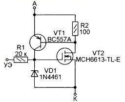
Fig. 8
Since the input resistance of the control electrode is large, it is prone to interference, which can lead to spontaneous opening of the SCRs. To reduce the input impedance, it is recommended to connect between the control electrode and cathode resistor 51 ohms. In this case, the SCR will open when the voltage on the control electrode above 1.4 V.
LITERATURE
- Moll J. L., Tanenbaum M., Goldey J.M., Holonyak N. P-N-P-N Transistor Switches. — Proc. of the IRE, 1956, Vol. 44, Iss. 9, p. 1174— 1182.
- Leipold L., Stengl J. P., Tihanyi J. FET
controlled thyristor. — Patent USA 4502070. Pend. 22.06.1981. Res. 26.02.1985.
- Temple V. A. K. MOS-Controlled Thyristors. — IEEE Electron Devices Meeting, Abstract 10.7, 1984, Vol. 30, p. 282-285.
Author: М. ШУСТОВ, г. Томск
Source: Radio No. 12, 2016