The proposed device disconnects from the mains power electronic devices, switched in stand-by mode, which increases the safety of operation and saves energy.
Основное отличие этой конструкции от автоматического выключателя (Нечаев И. “Автоматический выключатель бытовой радиоаппаратуры”. — Радио, 2016, № 7, с. 38) — использование вместо кнопки “Пуск” любой из кнопок ПДУ питаемого через неё аппарата.
The scheme of my circuit breaker shown in Figure. 1. Supply unit in it is made by the classical scheme with a step-down transformer T1, a rectifier diode bridge VD1, and the integral voltage stabilizer DA1. Part of the switch also comprises a receiver of infrared radiation TSOP31236 (B1), a logical node on the microcircuits K561LA7 (DD1), K561TM2 (DD2) and NE555N (DA2), threshold current sensor based on Hall sensor К1116КП4 (B2). For switching power supply circuit protected by the circuit breaker equipment applied optosymistor (solid state relay) S202S01 (U1).

Figure. 1
After power on the output of the trigger DD2.1 the original is discharged through the capacitor C4 will be set to low logic level, so the transistor VT2 and optosymistor U1 will remain closed, and fed via circuit breaker the equipment is de-energized. If using IR remote control to apply any command, the signal output of the receiver the IR radiation B1, proinvestirovany logic element DD1.1, set the trigger DD2.1 in a state with a high level at the output that opens the VT2 transistor and optosymistor U1. Now the instrument is connected to the network.
At the same time through the element DD1.2 and the circuit C8R2 on a single-shot integrated timer DA2 will be pulse start. The re-launch of the one-shot signal the remote control is prohibited by the signal from the output of the timer through the element DD1.3 to the terminal 6 of the element DD1.2.
The pulse duration of the one-shot is determined by the formula T=1,1R6C5. If specified in the diagram the resistance values of the resistor R6 and the capacitance of the capacitor C5 it is about 10 C.
В отсутствие сигнала с датчика тока (вся аппаратура выключена или находится в дежурном режиме) транзистор VT1 постоянно закрыт, поэтому по окончании импульса одновибратора триггер DD2.1 возвратится в исходное состояние. Если в цепи сетевого питания аппаратуры протекает ток, больший порогового значения, импульсы с выхода датчика В2 периодически открывают транзистор VT1, что разряжает времязадающий конденсатор С5 и “затягивает” импульс одновибратора на всё время, пока аппаратура включена.
Design sketch of the current sensor shown in Figure. 2. Его магнитопровод 2 типоразмера Ш6х6 набран “вперекрышку” из пластин электротехнической стали. Один из узких кернов магнитопровода, показанный штриховыми линиями, отрезан. Во втором таком же керне сделан зазор длиной 2 мм, в котором установлен датчик Холла 5. Чувствительная зона датчика (квадрат 2,5×2,5 мм — в центре его поверхности) должна быть расположена на оси керна. Обмотка 1 (на схеме обозначена L1) намотана проводом ПЭВ-2 диаметром 1 мм на широком керне магнитопровода и содержит 30 витков.
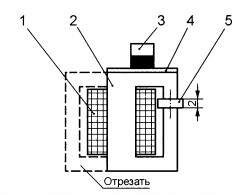
Fig. 2
Датчик тока можно изготовить и из трансформаторной стали другого типоразмера. Подготовленные пластины соберите в пакет толщиной 4…6 мм, в зазор вклейте микросхему К1116КП4, а на среднем керне намотайте 30—50 витков любого изолированного провода. Сечение этого провода по меди следует выбирать исходя из суммарного тока, потребляемого всей аппаратурой, которую предполагается защитить выключателем, и его плотности 3…3,5 А/мм2.
Threshold made me sensor current of 0.4 A. To obtain such a threshold with a coil of a small number of turns on the magnetic core 2 through the non-magnetic (textolite) spacer 4 of 1 mm thickness installed neodymium magnet 3 diameter of 6 mm and a height of 5 mm. Direction field of the magnet and its position on the yoke are selected experimentally for normalization.
Все детали выключателя (за исключением трансформатора питания и датчика тока) смонтированы на печатной плате размерами 85×50 мм из фольгированного с двух сторон стеклотекстолита. Чертёж платы показан на Fig. 3. It is designed for installing resistors C1-4 power 0.25 W, capacitors K10-17B and electrolytic capacitors C50-35.
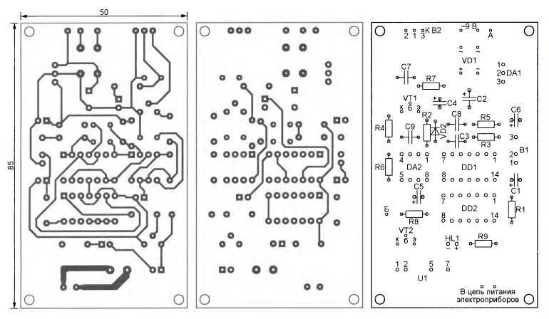
Fig. 3
Instead of solid state relay U1 in the design, you can use electromagnetic. In this case, the solid state relay is not set, and is intended for terminals 1 and 2 holes soldered a resistor 330-510 Ohm. Electromagnetic relay TR90-12VDС-SC-A1 is connected according to the scheme shown in Fig. 4.

Fig. 4
To test the sensor turn on the current in its winding network of ~230 In series with the incandescent bulb of about 100 watts. Giving the Hall sensor a 5 V supply, check with an oscilloscope the presence of a pulse a low logic level at its output. The greater the duration of these pulses, the more sensitive the sensor. The threshold of its operation is controlled by changing the position of the magnet in the magnetic circuit and the selection of the number of turns of the winding. The required threshold depends on the switched switch on the equipment with the least consumption in the operating mode current.
Measured by a galvanometer Ц4353 supply current running TV — only 0.2 A, but the switch with the described sensor reliably triggers from him. This is probably due to the fact that quiescent current has a pulsed character, as the amplitude of these pulses exceeds 0.4 A. In standby mode, the current consumption of the TV is reduced to 17 mA. The current consumed by the switch in standby mode does not exceed 2.5 mA and mostly depends on the quality of the transformer T1. I used the transformer TPP-3 220/9 In on a toroidal magnetic core.
In the course of work on the design revealed the unpleasant feature of the receiver of infrared radiation ТЅОР31236 — low noise immunity. This led to the inclusion of the TV without a signal from the remote controller. To eliminate this phenomenon, the output of the receiver included integrating circuit of a resistor R3 and capacitor C3. I want to note that removed from old equipment receivers IR radiation DHR38N, 27N2Y2 more noise immune. They worked reliably without the suppression circuit.
Пользоваться выключателем очень просто. Первое нажатие на любую кнопку ПДУ активирует выключатель, загорается светодиод HL1, информирующий о включении питания аппаратуры. Если в течение 10 с после этого никаких нажатий на кнопки ПДУ не было, по их истечении питание будет выключено и выключатель вернётся в режим ожидания. Если же за это время нажатием на кнопку “Power” ПДУ аппарат, которому адресована эта команда, был приведён в действие, питание останется включённым. На последующие команды и включение-выключение других аппаратов выключатель реагировать не будет, пока суммарный потребляемый всеми действующими аппаратами ток не упадёт ниже порога. Через 10 с после этого выключатель отключит сеть и перейдёт в режим ожидания, в котором будет оставаться до нового нажатия на кнопку ПДУ.
Author: N. SALIMOV, Revda, Sverdlovsk region.
Source: Radio No. 12, 2016