This article describes a memory that can simultaneously charge and desulfatace car battery over a specified period of time. During operation of the electric battery sooner or later will be exhausted. Battery charge is performed, as a rule, one of two methods: constant current or constant voltage. In the first case the charge is constant current of 0.1 C (0.1 of the nominal capacity of the battery). For a battery capacity of 55 Ah charging current is 5.5 A. in fact, the charging device is an adjustable current regulator.
При заряде постоянным напряжением степень заряженности аккумуляторной батареи напрямую зависит от величины зарядного напряжения. Полностью зарядить батарею можно при напряжении зарядного устройства 16,3…16,5 В. В первый момент включения тока его величина может достигать до 50 А и более, в зависимости от внутреннего сопротивления батареи. По мере заряда напряжение на ее выводах приближается к напряжению зарядного устройства, величина зарядного тока соответственно снижается и приближается к нулю в конце заряда. Критерием заряда в подобном случае является достижение напряжения на выводах АКБ равного 14,4 ±0,1 В.
Schematic diagram of the charging device (hereinafter the device) is shown in Fig.1.
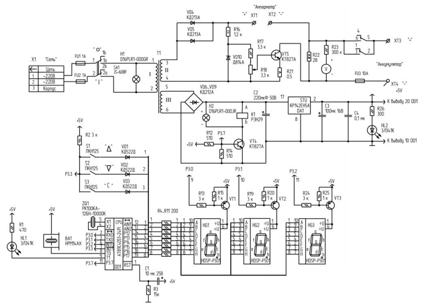
Figure. 1
The device provides a pulse charging current up to 10 A. For charging and simultaneous desulfuratsii battery it is advisable to install a pulse charging current of 5 A.
The device contains three main functional units:
- the current regulator, performed on the transistor VT5;
- the timer on the microcontroller DD1;
- the voltage regulator on the chip DA1 to power the timer.
Заряд аккумулятора осуществляется положительными импульсами тока с обмотки II трансформатора Т1, в течение половины периода сетевого напряжения, когда напряжение на клеммах ХТ3, ХТ4 превысит напряжение на аккумуляторе. В течение второго полупериода диоды VD, VD5 закрыты, и аккумулятор разряжается через нагрузочное сопротивление R22. Величина разрядного тока определяется номиналом данного сопротивления. Значение зарядного тока устанавливается вращением движка резистора R22 по амперметру, подключаемого к клеммам ХТ1, ХТ2. Учитывая, что при зарядке батареи часть тока протекает и через резистор R19, то показание амперметра должно быть 1,8…2 А (для импульсного зарядного тока 5 А), так как амперметр показывает усредненное значение тока за период, а заряд осуществляется в течение половины периода.
The voltage reference is the Zener diode VD10. Reference voltage via the divider R17R18 is supplied to the base of transistor VT5.
Voltage is supplied to the winding I of the transformer T1 through fuse FU1, FU2 and the switch SA1. Light bulb H1 allows you to visually control the network voltage. Main technical specifications of the battery charger is given in table.
The scheme provided protection from uncontrolled battery discharge in case of loss of mains voltage. In this case, the relay K1 and their contacts will disconnect the circuit of discharge of the battery. Protection against short-circuit, the device has a fuse FU3. The +5V power supply includes a rectifier diode VD6-VD9 and voltage stabilizer DA1. The voltage at the rectifier is supplied with the winding III of the transformer T1. Indicator HL2 allows you to visually control voltage +5 V.
Timer
A countdown timer implemented in the microcontroller DD1. Set time from 1 to 999 minutes from the pump 1 min., Provides delivery (duration 60 seconds) audible signal at the end of the reference specified period of time. The operating frequency of the microcontroller is set by the generator with external resonator ZQ1 with a frequency of 10 MHz.
Relay K1 controls the transistor VT4, and the signal which comes from pin 11 of the microcontroller DD1. The piezoelectric emitter BA1 is connected to pin 8 of the microcontroller DD1. Indicator HL1 is included with the terminal 9 of the microcontroller DD1.
With the port P1 of the microcontroller DD1 interrogates the keyboard (buttons S1-S3), and controls dynamic display on the transistors VT1-VT3 and digital seven-segment displays HG1-HG3.
For the functioning of the keyboard involves the output 7 of the microcontroller DD1. The digital part of the schematic diagram (timer) galvanically isolated from the mains 220 V/50 Hz and an analog part (current regulator).
The device interface consists of the keyboard (buttons S1-S3), the indicator light HL1, light bulbs H1, H2, and a display unit (display) of the three digital seven-segment indicators HG1-HG3. The interface is compact, convenient and has good readability. The keypad buttons have the following purpose:
- S1 ( Д ) – увеличение на единицу значения при установки времени в минутах, при удержании данной кнопки в на жатом состоянии более 4 с, значение времени, индицируемое на дисплее, увеличивается на 5 единиц за 1 с;
- S2 ( С ) – уменьшение на единицу значения каждого при установке времени часов, работает аналогично кнопке S1;
- S3 ( C ) – кнопка включения/выключения выпрямителя, данная кнопка подтверждения заданных параметров и начало работы, с нажатием данной кнопки начинается работа таймера – идет обратный отсчет заданного времени, включается реле К1 (лампочка Н2), включается также индикатор HL1.
| Specifications | Option |
| The network voltage, V | 220 ± 10%, 50 Hz |
| Power consumption, W, not more | 170 |
| Specified charging current pulse, And | to 10 |
| Overall dimensions, mm | 245 x 115 x 110 |
| Weight, kg not more | 5 |
| The maximum charge time, min. | 999 |
| The discreteness of the task, min. | 1 |
The digit display interface have the following designation:
- разряд (индикатор HG1) – «единицы минут»;
- разряд (индикатор HG2) – «десятки минут»;
- разряд (индикатор HG3) – «сотни минут».
Immediately after power-on at pin 1 of the microcontroller DD2 through the circuit R3C1 signal is generated system hardware reset of the microcontroller DD1. When you initialize a piezoelectric emitter BA1, the indicator HL1, transistor VT4 is disabled. Indicators HG1-HG3 are indicated zeros. H-point indicator HG3 included. To put the device to operating mode it is necessary buttons S1 (D) S2 (C) set the desired interval time. When setting the time, countdown timer prohibits the current time. Then you need to click the S3 button (S), this activates the indicator light HL1, light bulb H2, the pin 11 of the microcontroller will be set to log. "1". The VT4 transistor opens and the voltage from the rectifier diode VD6-VD9 will include a relay K1, their contacts which complete the circuit connecting the battery. The procedure starts with the charging of the battery. The set time is stored in the memory of the microcontroller DD1.
The time displayed on the indicators HG1-HG3, decremented every minute. H-point indicator HG3 flashing with a period 1 s. If you want to stop the charge and change the time, press the S3 button () will turn off the indicator light HL1, light bulb H2 and the relay K1, their contacts which opens the circuit connecting the battery. Then buttons S1 (D) S2 (C) set the desired interval time and press the S3 button (S).
Software microcontroller fully ensures the implementation of the algorithm of the electronic clock. The formation of precise time intervals with a duration of 1 second, solved using interrupt TF0 timer and the counter to the register R3. The counter for the register R4 forms an interval of one minute. TF0 timer generates interrupt request at intervals of 3400 ISS. Counters in these registers count the number of interrupts, and after each minute a flag is set (pusk1), and the current time decremented.
Adjust the current time every ten minutes. The interval for the timer TF0 3400 ISS chosen by chance. Every 3400 ISS is the mapping of digits in the dynamic display device.
The program consists of three main parts: initialization, main program, running in a closed loop, and the subroutine processing timer interrupt TF0.
The design and details
Transistor VT5 should be installed on the radiator. Area effective heat sink surface is not less than 200 cm2. DA1 chip is also installed on the radiator. The area of the effective surface of a radiator is at least 20 cm2.
Fork X1 is part of the power cord SHVVP-ВП2 x 0,75-250-18-6.
В устройстве применены резисторы типа С2-33Н-0,125, резистор R16 – С2-33Н-2, R18 – СП5-2ВБ, R21 – С5-16МВ (автор последовательно включил два резистора С5-16МВ-2Вт-0,2 и один С5-16МВ-2Вт-0,1), R22 – ПЭВ-30. Подойдут любые другие с такой же мощностью рассеивания и допуском ±5%.
Capacitors C1-C3 of the type K50-35. The capacitor C4 type K10-17A. This capacitor is installed between a circuit +5 In, and overall conductor of the microcontroller DD1 directly near IC.
Стабилитрон VD10 подойдет любой, с напряжением стабилизации от 8 до 12,2 В. Реле К1 – РЭН29 РФ0.450.016ТУ на напряжение 12 В.
The transformer T1 is made on the yoke SHL 32х40 (Э310 material thickness 0.35 mm). Primary winding of I contains 554 loop of wire PETV-2 of 0.8. Winding II contains 132 round wire PETV-2 is 1.6, with a tap on coil 66. III winding consists of 30 turns of wire PETV-2 of 0.8. The windings are laid between three layers of varnished cloth LMLS-105-0.12 GOST 2214-78 coil wrapped with three layers of varnished cloth above.
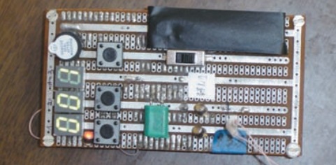
Fig. 2
This transformer can be replaced by another with the following parameters:
- Максимальная выходная мощность, не менее …. 200 Вт;
- The voltage of the secondary winding II:
в режиме «холостого хода» …. 22…25 В;
в режиме номинальной нагрузки …. 21.24 В;
- The voltage of the secondary winding III:
в режиме «холостого хода» …. 12В;
в режиме номинальной нагрузки …. 11В;
- Максимальный ток обмотки II …. 8А;
- Максимальный ток обмотки III …. 1А;
- Электрическая прочность между первичной и вторичными обмотками …. 1,5 кВ;
- Сопротивление изоляции …. 500 МОм.
Note that the current consumption through the channel of +5 V is not more than 200 mA.
Номинальный ток предохранителей FU1, FU2 – 1,1 А. Тип ВП1-1,1А (1,1 А/250 В). Держатели вставок плавких типа ДВП4-1в. Номинальный ток предохранителей FU3 – 10 А. Тип ВП1-2 (10 А /250 В). Держатель вставки плавкой типа ДВП4-2В.
Электромонтаж цепей стабилизатора тока велся сдвоенным проводом МГШВ-0,5. Монтаж цепей таймера проводом МГТФ-0,12, монтаж остальных цепей проводом МГШВ – 0,35.
Working with device
It is advisable to test the device in a resistive load. For this it is necessary to terminals ХТ3, ХТ4 connect a resistive load of 6 ±1 Ohm (Rraces=60 W, I=6 A) suitable rheostat type RSP 15 ±10% Ohm at 6.5 A. To the terminals ХТ1, ХТ2 to connect an ammeter (with a limit of any current measurement up to 10 A). Enable the switch SA1 and set, rotating the engine the resistor R18, the current on the ammeter 1.8 A (for pulse charging current is 5 A, so that the ammeter shows the average value for the current period).
Через 2…3 ч работы проверить тепловой режим работы устройства и показания амперметра. После подключения аккумуляторной батареи, значение зарядного тока резистором R18, по амперметру, нужно установить в пределах 1,8…2 А.
Author: Sergey Shishkin, Sarov
Source: the journal Elektrik, No. 10, 2014