Currently, radio Amateurs have become very affordable low-cost and high-quality displays from (for) mobile phones. For specific opportunities use one of them in different Amateur designs the author has created a module, which is described in this article. The author believes their development is perfect, but hopes that this module will be used by radio Amateurs. Tips and suggestions for improvement are accepted.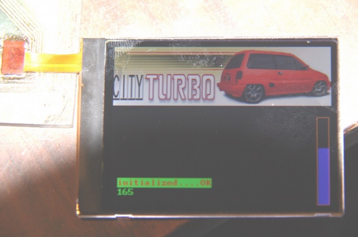 To use in their construction of a miniature color display that does not need particularly powerful processors or expensive displays. If you need a screen size of about 2.5”, it is possible to apply the display from the phone. For example, LS022-LS024 from NOKIA phones N76, N82, N73, 6303, 6500. And fit the biggest display from the N95 (2.6”).
All these displays feature a controller with a small but fairly complete, set of commands. Datasheet for the display controller MC2PA8201, which is similar to LS022-LS024 attached. However, not all functions work 100% as described.
The display has a resolution of 240x320 pixels and color 24 bit. Cost from 200 rubles. Connector Flex cable is the same. Ragged plume of renovation can give away for free. A well-known difficulty is only the soldering and manufacturing under his charge.
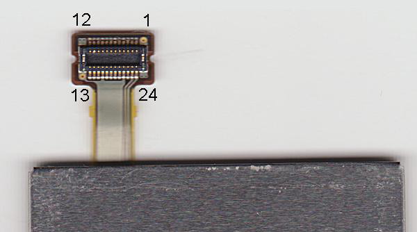
The display has three supply voltages: 1.8 V, 2.5 V and 12 V. the Latter is illuminated through the limiting resistor. The current illumination is approximately equal to 20 mA. The Pinout of the connector shown in figure N76.1.

Figure. 1
This connector looks like this:
 Examples of this display in the network there quite a lot. Using them, I designed and assembled module as a template for creating its graphical user interface. Diagram of the module shown in Fig.2.
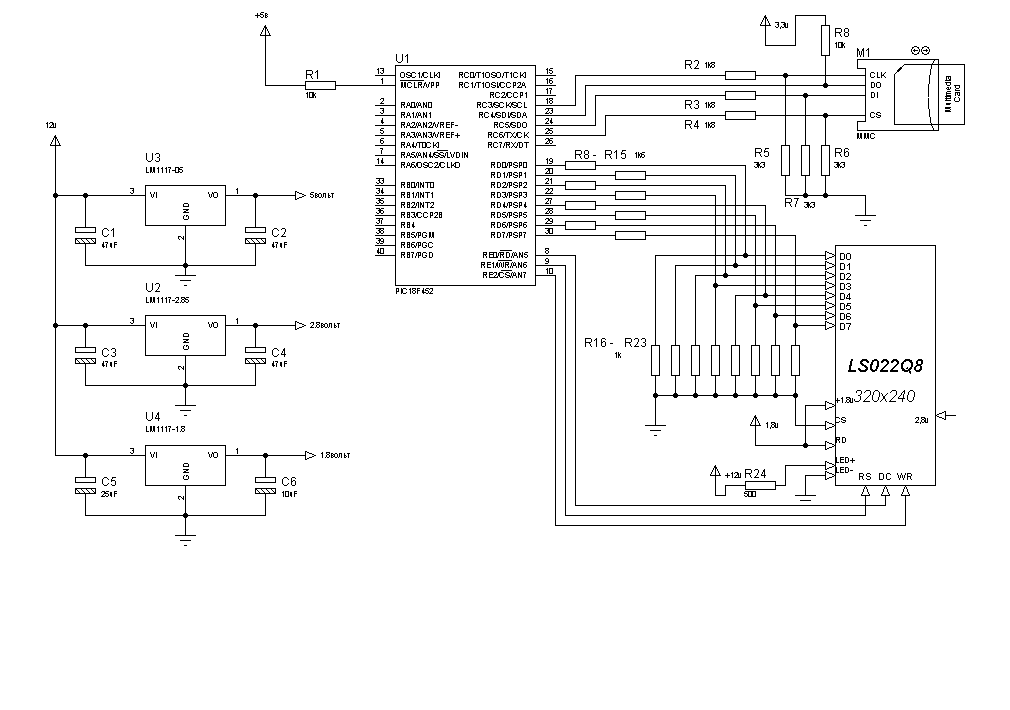
Fig. 2
The Foundation module is common microcontroller PIC18F452. The program for it written in C.
To power the display I used two stabilizer LM1117 to the appropriate voltage. Nominal voltage on signal lines of 1.8 V.
With a simplified connection (via divider resistors) that I used for level matching output signal YC and the input of the display cannot be read from the display memory, but it is not needed. However, if you want, you can apply a more correct alignment of these levels.
Inductance in power circuits used in the circuit of the phone, I think, can be ignored since the phone utilizing the pulsed power converters and the I linear.
The advantage of the considered display, as his problem is a 24-bit color. That is, to output 1 pixel it is necessary to transmit 5 bytes, which reduces throughput and requires a decent volume to store images. Therefore, the clock speed of the processor should try to choose as high as possible. I used 40 MHz. The speed of drawing is quite satisfied, and the output speed of the image is too small. Alternatively, at the time of drawing large screensavers to make your screen.
Images, screensavers, icons, choose to store on the microSD card. Small now very few sells, but cost quite a penny, enough to spare, and the convenience lies in the ease of editing displayed elements directly in the computer .bmp files. Subsequently, the card can be used to record, for example, log any events.
The attached program has a library of the necessary graphics functions (described in the file LS_driver.h):
- the output point;
- the output symbol;
- text output;
- output of byte values;
- drawing the line;
- to draw a rectangle (filled or not);
- drawing a circle;
- drawing of box-type WINDOWS;
- reading from cards and drawing .BMP 24bit/pix
Detailed instructions on the functions outlined in the file LS_driver.h, and not particularly self-explanatory, with the exception of 2 points.
- If the output image should adhere to the vertical orientation of the screen (the picture file pre-deploy in the editor).
- In the output file and drawing pictures you should consider the size of the screen. The values of X and Y are swapped when changing the current orientation output from horizontal to vertical and Vice versa, so check on the abuse of size is not possible (not known to the current maximum X or Y).
All this, of course, long been known, but I tried to keep it together.
Was more or less universal module that can be embedded in the finish or design.
In the interface card locked optional, in my opinion, options: directory, entry, support FAT32, but you can enable them at any time.
As an example, given the drawing of the vertical scale depending on the value of the ADC (see title photo). At the top of the screen displays the picture – saver.
Author: Sergey Shakurov, Moscow