When the personal computer is in standby mode, often together with him remain connected to AC mains 220 V various loads, for example, the monitor, the power amplifier of audio frequency, printer, scanner, modem, external hard drives. This not only leads to useless power consumption, but also shortens the lifespan of computer peripherals. To avoid this, you can make a simple device that will disable the computer peripherals from the power supply while the computer was not working.
Schematic diagram of the control device loads presented in Fig. 1. Unlike similar purpose constructions [1], this machine can work with computers that are in standby mode, the voltage of +5 V to the USB ports is always there when the computer's power supply receives a voltage of 220 V, and in the case when in standby mode, the voltage of +5 V from the USB port of the computer is turned off. Not all computer motherboards allow you to configure USB ports to the +5V in standby mode is not filed.

Figure. 1
This device works on the principle that in standby mode the ripple amplitude supply voltage +5 V is much less than when the computer is running even when there is no serious load on the CPU and graphics card. The device connects to the USB output port of the computer. Thus the signal lines of the USB are not used. Supply voltage +5 V is supplied to low-voltage low-power nodes through a decoupling choke L1, the Capacitor C1 serves to filter the supply voltage. The voltage ripple of pinii +5V supply through the resistor is supplied to the sensitivity done on trimming the resistor Then through the separating condenser Sz voltage pulsation is supplied to the two-stage low-frequency amplifier, made on bipolar transistors VT1, VT2. Both of the cascade transistor included in the circuit with common emitter auto-bias. The first amplifier stage is supplied with the voltage +5 V through a filter R4C4. The capacitor C2 ensures that the input of the ULF frequencies.
В случае, когда компьютер находится в дежурном режиме, амплитуда напряжения на выводе коллектора VT2 не превышает 0,5 В, конденсатор С8 разряжен, полевой транзистор VT3 закрыт, оптосимистор U1 закрыт, мощный симистор VS1 закрыт, нагрузка обесточена. Как только будет включен компьютер, амплитуда пульсаций напряжения +5 В на выходе USB порта резко возрастёт до 20…50 мВ. Амплитуда напряжения на выводе коллектора VT2 возрастёт до 3…4 В, конденсатор С8 зарядится до напряжения около 4 В, полевой транзистор VT3 откроется, откроется оптосимистор оптрона U1, вместе с ним в начале каждой полуволны сетевого напряжения 220 В будет открываться симистор VS1, на подключенные нагрузки поступит напряжение питания 220 В, В это время будут светить контрольные светрдиоды HL1 и HL2. Резисторы R10, R18 ограничивают рабочий ток через светодиоды. Диодный мост VD3 – VD6 выпрямляет напряжение для питания HL2. По два токоограничительных резистора R11, R13 и R15, R16 включены парами вместо одиночных резисторов для того, чтобы уменьшить негативные последствия в случае пробоя изоляции оптрона U1. Применение кремниевого диода VD2 вместо желаемого германиевого необходимо для уменьшения обратного тока, чтобы конденсатор С8 не разряжался через этот диод.
After reducing the amplitude of the voltage ripple +5 V, for example, the computer was put to sleep, the capacitor C8 begins to discharge through a high resistor R9. When the voltage on the plates of the capacitor will decrease so that the transistor /TK will be closed, will open the VT4 transistor and through a resistor R12 C8 will quickly discharge. The load will be de-energized. The exposure time depends on the parameters of timing circuit С8R9 threshold voltage and opening applied to the field effect transistor. If specified in the diagram will be about 8 minutes. This time is chosen in order to avoid accidental shutdowns of the connected load during operation of the computer or when it reboots. To reduce the exposure time, it is advisable to install a capacitor C8 a smaller capacity.
High-current part of the device is made of calculation that the load to the output device can be connected to powerful loads, for example, a laser printer. The varistor protects the load from voltage spikes on the network. Two-winding inductor L2 and inductor L3 reduces the level of noise coming to the load from the network 220, and also, reduce the maximum pulse current at the time of opening of the triac, which can have dangerous DPJ triac values due to the presence of anti-interference capacitors input power supply of the connected loads, having in its composition pulse bpoke power. Resistor R19 prevents the illumination of the led НL2 when off load, the Resistor 18 together with the circuit for the led НL2 also simulates the presence of a load at the output, thus preventing, when the device is in standby mode, the fuelling is connected to the output of the machine low current loads, such as electroluminescent lighting compact lamps with electronic ballast.
Все детали конструкции кроме плавких предохранителей могут быть смонтированы на печатной плате размерами 140×60 мм, Figure. 2.
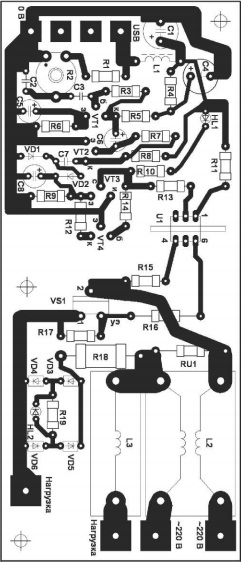
Fig. 2
Для более компактного исполнения устройства печатную плату можно разрезать надвое примерно посередине — отдельно слаботочные и силовые узлы, как это сделать видно по характеру рисунка дорожек. Усилительные каскады на транзисторах должны быть обязательно экранированы, для чего на монтажной плате из тонкой латуни или пищевой жести паяют шестистенную «коробочку-экран». Постоянные резисторы можно применить любого типа, например, С1-4, С1-14, С2-23, С2-33, МЛТ, РПМ. Подстроенный резистор СП5-16ВА, СП4-1, РП1-63М или импортный малогабаритный аналог сопротивлением 1,5…4,7 кОм. Вместо дискового варистора FNR-20К471 можно применить FNR20K431, МYG20-431, МYG20-471, LF14К471. Для повышения степени защиты нагрузок от аномальных напряжений можно подключить 2-4 одинаковых варистора параллельно. Неполярные конденсаторы малогабаритные плёночные или керамические. Оксидные конденсаторы К50-35, К50- 68, К53-19, К53-1 или аналоги. Германиевый диод ГД507А можно заменить любым из 1Д507А, Д9, Д18 или диодом Шотки 1N5817 – 1N5819, МВРS140TR, SFPB-56. Кремниевые диоды КД521А можно заменить на любые из серий КД503, КД510, КД521, КД522, 1N914, 1N148, 1SS244. Светодиоды АЛ307ЛМ можно заменить любыми непрерывного свечения с повышенной светоотдачей, например, КИПД66Е2-К, КИПД35Л-К. Вместо транзисторов КТ3102Г можно применить любые из серий КТ3102, КТ342, КТ6111, КТ6113, КТ645, ВС547, SS9014, 2SС3199, 25С1845. Полевой транзистор КП505Г можно заменить любым из серий КП505, КП504, ВSS295. Симисторный оптрон S21МЕЗ можно заменить на S21МЕЗF или имеющим узел детектора нуля S21МЕ4, S21МЕ4F. Симистор MAC16N рассчитан на ток нагрузки до 15 А. Он должен быть установлен на дюралюминиевый теплоотвод размерами 58x30x4 мм. Теплоотвод изолируют от теплоотводящего фланца симистора. Для упрощения монтажа можно применить один симистор, выполненный в изолированном корпусе, например, МАС320А8FР, МАС320А6FР, МАС320А10FР, МАС228-6FР, МАС228А6FР, МАС228-8FР, МАС228А8FР, МАС212А8FР, МАС212А10FР. Для установки симистора на теплоотвод применяют теплопроводную пасту КПТ-8. Дроссель L1 малогабаритный промышленного изготовления индуктивностью 1000…6800 мкГн с сопротивлением обмотки 1…4,7 Ом, дроссель со цветовой маркировкой индуктивностью 1000 мкГн будет иметь, начиная с торца, коричневую, чёрную и красную полосы. Другие дроссели выполнены на кольцах К32х20х9 из феррита HM3000 без немагнитного зазора. Дроссель L2 содержит 18 витков сложенного вдвое монтажного провода с сечением по меди 1,3 мм кв. Предпочтительнее применять провод во фторопластовой изоляции. Дроссель L3 содержит одну обмотку из 18 витков такого же провода. Дроссели установлены вертикально. Держатели предохранителей типа ДП1-ЦМ или Д8П-7, установлены на корпусе устройства. Если предполагается подключать к устройстве нагрузку, потребляющую ток более 5 А, предпочтительнее вместо 20 мм предохранителей, применять плавкие предохранители в стеклянном или керамическом корпусе длиной 30 мм, для которых подходит держатель ДВП-7.
The unit is connected to the computer "without intermediaries" — directly to the USB port of the computer motherboard without using an active foreign U5B splitters, which may contain built-in filters power, which can make the device operation unstable. Current consumption from USB port will be about 3 mA when the device is in standby mode and about 30 mA when the load is energized. Customize design is reduced to the sensitivity is adjusted by resistor R2. Sensitivity set the maximum so that when the computer is off and is in standby mode, to avoid false positives. Because of the partial malfunction of the computer power supply may increase the ripple voltage of "duty" +5 V when the computer is off, which can lead to false switching on the power to the loads. This problem can be eliminated by replacement of problematic electrolytic capacitors in the power supply of the personal computer.
Literature:
- Butov AL. Power management computer peripherals. — Kit, 2011, №9, p.10.
- Butov AL. Two devices for the dependent inclusion of appliances. — Радиоконструктор, 2012, № 8, с. 21 – 21.
Author: Butov AL.