This thermostat is designed to work on lowering the temperature, including the fan when the temperature exceeds a predetermined limit.
Схема, можно сказать, стандартная, – термодатчик, схема для установки опорного напряжения, компаратор, выходной симисторный каскад.
Датчик используется промышленного изготовления, – LM335A2.
It can be described as the Zener diode, voltage stabilization and precision which is linearly dependent on the temperature. This sensor has a precise linear dependence 10mV per degree on the Kelvin scale. For example, at a temperature of 0ºC (273K) the voltage sensor of 2.73 V, and at a temperature of 70º(343К), respectively, of 3.43 V.
Sensor A1 is connected via two terminals and can be inside the body of the thermostat and the remote, mechanically fixed to the object the temperature of which must be controlled. In conjunction with resistor R4 it forms a parametric voltage regulator is temperature-dependent. This voltage is then fed to a direct input of the operational amplifier A2 via the RC circuit R1-C1-R2 to suppress interference and crosstalk which may take place at the location of the sensor at some distance from the scheme.

Figure. 1
On the inverse input of A2 receives a reference voltage, modifying the value of which set the threshold of on/ off of the heater.
The temperature fan switch set trimming resistor R6. In order to create hysteresis so that the fan does not turn on too often and especially his work did not go in any pulse mode, use the resistor R7. With his help, set the voltage offset at the input of A1 when turning on and off the fan. At the same time, when you turn on the fan the voltage at the input of A1 is increased, and when turned off, decreases. Capacitor C4 eliminates the self-excitation at high frequencies.
When the temperature is below the set value, the voltage at the input falls below the voltage on the inverse. Operational amplifier working as a comparator, sets their output low voltage, close to zero. The key transistors VT1 and VT2 is closed, and the VENT fan turned off.
If the temperature is above the setpoint, the voltage at the direct input of op amp A2 is higher than the voltage at the inverse input. The output of op amp A2 is set to the voltage close to its voltage. Transistor switch to VT1 and VT2 opens and the fan.
The voltage power supply corresponds to the nominal operating voltage of the fan (use the fan from a power source personal computer).
Напряжение, поступающее на цепи опорного напряжения и датчика стабилизировано с помощью стабилизатора А3. По аналогичной схеме можно сделать термостат для управления холодильной установкой или старым холодильником с исправным агрегатом, но неисправным термостатом. Такая схема показана на рисунке 2. Отличие только в выходном каскаде, – здесь вместо вентилятора подключено электромагнитное реле.
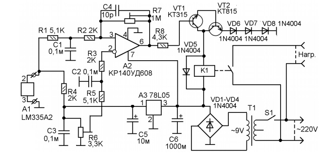
Fig. 2
The difference is in the power supply. The power supply of the electronic circuit is made on the transformer T1. Here we use the low-powered Chinese transformer with primary winding at 220V (with a tap from the middle, which is not used) and the secondary winding of 9V. Maximum current of secondary winding 100 mA.
AC voltage is rectified by the rectifier bridge VD1-VD4 and the capacitor C6 are allocated a constant voltage of about 12V.
The power source can be done on another transformer providing a secondary winding voltage of about 9 - 10V, for example, in TCEs from an old TV. Or you can use a network adapter with an output 12V DC voltage.
The operational amplifier may be replaced by another similar OU for General use, for example, К140УД6, К140УД7, КР140УД708, К140УД608, К140УД708 or imported.
The rectifier bridge can be assembled on other diodes, for example, 1N4005, 1N4006, 1N4007, 1N5404, 1N5405, 1N5406, 1N5407, 1N5408. Or use a diode bridge Assembly, for example, КЦ407, КЦ402, W04M or the other.
1N004 the rest of the diodes can be replaced by any equivalent, for example, 1N4005, 1N4006, 1N4007, 1N5404, 1N5405, 1N5406, 1N5407, 1N5408.
Transistor KT315 can be replaced by КТ3102, 2SC945, 2SC3199, 2SC815, 2SC1815, 2SC1845, ВС547, SS9014, КТ503, КТ645, КТ6113 etc.
КТ815 transistor can be replaced by КТ817, BD135, BD165, BD167, BD169, BD813, BD815, BD817, ТІР29, ТІР61 etc.
Type of electromagnetic relays in the circuit of figure 2 depends on the load you want to manage. If the unit is an old refrigerator, you can use automotive relay in a plastic housing, with a coil at 12V.
Trimmer resistors R6 and R7 preferably multi-turn, as the adjustment becomes quite sharp, besides multi-turn resistor because of its more stable design keeps the installed condition.
Networking is reduced to the setting of the voltage at the inverse input A1 of the trimming resistor R6 and the setting of hysteresis with R7
Author: Adamov I.