I'm going to show you two other examples of using NE555 timer (555).
You will need all the same components as for experiment 16 plus Extras:
- Another 555 timer chip. A total of 2 PCs.
- Miniature speaker. Quantity is 1 piece.
- Potentiometer with linear characteristic and resistance 100 kΩ. Quantity is 1 piece.
Procedure
Leave all components Experiment 16 at the location where you installed the breadboard, and add the following part of the circuit is slightly lower, as shown on the circuit (Figure. 1) and electric (Figure. 2) schemes. These schemes between the 6 and 7 chips instead of jumpers, which zakorachivala these findings in the previous diagram, the resistor R2 is inserted, and the external circuit run using 2 output is no more. Instead, the withdrawal of the 2 jumper connected to conclusion 6. The easiest way to do this is to lay a wire jumper from the top of the hull.
 Figure. 1. These components must be added to the same layout cost just below the components, which are shown in Experiment 16. The following values should be used for testing the 555 timer chips in avtokolebatelnom mode: R1 is the resistance of the resistor 1 KOhm; R2 is a resistor with resistance 10 kohm; R3 is a resistor with resistance 100 ohms; C1-0.047 µF capacitor (ceramic or electrolytic); C2 — 0.1 µF capacitor (ceramic); ІS2-555 timer chip
From the diagram, shown in Figure. 2I removed the smoothing capacitor, because I assume that you collect the second part of the scheme on the same Breadboard that first, where there is already a smoothing capacitor C3.
 Figure. 2. It is a variant of the above wiring diagram circuit diagram in Figure 1. 1. Values and designations in schemes for the same.
The speaker connects consistently rezistoru with resistance 100 ohms (3), which replaced the led showing the availability of the output signal. Conclusion 4 (reset) connect directly to the positive power source, as in this diagram reset function I use is not going to do.
So, what happens if the supply voltage? You should immediately hear the hum from the speaker. If you haven't heard, then it definitely is a consequence of connection errors.
It should be noted that it is now using the button, you cannot change the status. The reason is that the capacitor C1 is charged and discharged, and his changing voltage connects via a jumper from the top of the hull, found chip 2 (start). Thus, the 555 timer switches on their own.
In this case, the chip works in avtokolebatelnom mode. Avtokolebatelnyj — means that it is not stable, as infinitely switches that in one in a different State, sending pulses throughout the time until the circuit is connected to a power source. The pulses are so brief that you can hear in a constant hum.
The actual values of the components that I asked using the R1, R2 and C1 to 555 timer chip to generate pulses with a frequency of 1500 pulses per second. In other words, creates the sound with a frequency 1.5 kHz.
Look at the table. 1 to see how very different values of R2 and C1, create pulses of different frequency in "avtokolebatelnom" mode. It should be remembered that this table is designed with a fixed resistance value of the resistor R1 equal 1 com!
|
Basic information |
The following table. 1 Displays the calculated Cha stotu autooscillations 555 timer chip ble ble the values vremjazadajushhih components: capacity con densatora C1 and the resistance of the resistor R2 while resistance R1 resistor value equal to 1.
To calculate the varying frequency: need to redouble resistance resistor R2, add to it the resistance R1, multiply this amount by the amount of capacitance C1 and divide the result by 1440. Thus we get: Frequency of self-excited oscillations = 1440/((1 + 2R2) × C1) periods of oscillations per second. In the formula for the resistance of resistors R1 and R2 are in kiloomah (com), the capacity of the capacitor C1 in mikrofaradah (ICF), and the frequency in Hertz (Hz) (number of vibrations per second). It should be noted that the period of oscillation is measured from the beginning of one pulse and before the start of the next. The duration of each pulse is not equal to the duration of the interval between each pulse. Table 1
|

|
Theory |
| Inside the 555 timer. Avtokolebatelnyj mode
Now what happens, shown in Fig. 3. Initially, as it was earlier in odnovibratora mode, trigger FF (RI sunke shown as a radio button) "on the ground" internally, i.e. "-" power supply capacitor C1. But now this low voltage capacitor on outside wire comes with 7 output found 2. This indicates low voltage chip, that she should switch itself. Trigger obediently switched to the bottom of the diagram the status "enabled", and sends a positive impetus to the speaker, while disabling the negative voltage output 7.
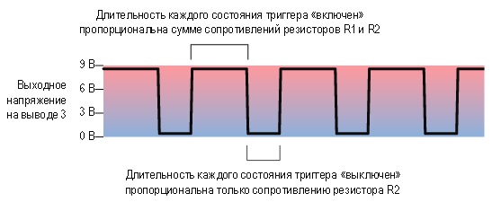
Now starts charging capacitor C1 is the same as it did in monostabilnom mode, instead of charging through consistently connected resistors R1 and R2. Because the resistors have a relatively low value resistance and capacitor C1 small capacity, it is recharged fast enough. When the voltage on the capacitor, the same as previously, will reach 2/3 full voltage, comparator is triggered, switching trigger in the top of the diagram off position, discharging capacitor and stopping the flow of positive momentum through output 3. The condenser requires more time to discharge, than it was before, because now the resistor R2 is connected between the capacitor and the withdrawal of 7 (level). While capacitor discharges, voltage decreases, but using the wires remain connected to conclusion 2. When this voltage drops to 1/3 of the full supply voltage, or a little less, triggered a comparator switches trigger, starting the process over again. Let's summarize. 1. In avtokolebatelnom mode, as soon as the supply voltage is connected to the chip, the trigger is in the initial state reduces the output voltage 2, forcing the comparator trigger and trigger that switches (switch) the bottom position of the scheme. 2. The output chips (3) high-level signal (+ power supply). Through resistors R1 and R2 connected in series, starts charging capacitor C1. 3. When the capacitor voltage reaches equal voltage 2/3, trigger switches in the upper State of the schema and the output (output 3) again comes the low level voltage. Capacitor C1 again begins to discharge through the resistance of R2. 4. When the voltage on the capacitor becomes less 1/3 the full supply voltage, the output voltage decreases correspondingly 2, which leads again to trigger switch in the lower position of the scheme, and the cycle repeats. Different trigger State durationWhen the timer works in avtokolebatelnom mode, the capacitor C1 is charged via consistently connected resistors R1 and R2. But when the capacitor C1 is discharged, it does only through resistor R2. This means that the capacitor is charging more slowly than discharges. During charging the capacitor voltage at pin 3 remains high; During level will be low. Therefore, the trigger status "enabled" always "off" State longer. On Figure. 4 This is shown in the form of a simple temporal graph.
If you want the duration to one and other conditions were identical, or you wish to independently regulate the duration of these conditions (for example, to transmit a very short pulse to another chip, which until the next impulse should follow big pause), then all you need to do is just add one diode as shown in Figure. 5.
Now, when the capacitor C1 is charged, his current charge actually is determined only by the resistance of the resistor m, because the resistor R2 shorted diode D1, included in the forward direction. When the capacitor C1 is discharged, the diode current level turns out to be included in the reverse direction, and therefore discharge only through resistor R2. So, in this scheme, charging time of capacitor is determined only by the resistance of the resistor R1 and the discharge time is only the resistance of the resistor R2. The formula for the calculation will be as follows: Frequency = 1440/((R1 + R2) x C1). If you specify the same value resistances of resistors R1 and R2 (R1 = R2), you must obtain almost the same duration generated pulses and pauses in between ("almost" because there is a diode, though small, but voltage drop of about 0.6 In). The exact value of this voltage depends primarily on the technology that was used in the manufacture of diode, or rather from the applied material (Silicon or, for example, Germany). |


Finishing the timer schemes operating in avtokolebatelnom mode
If the schemas shown in Figure. 2 or 5you instead of the resistor R2 set the potentiometer resistance 100 kΩ, you're turning it axis, will get a chance to change the oscillation frequency in one direction or another.
Another opportunity to "tune" the timer is using 5 "output control voltage, as shown on the Fig. 6. Отсоедините конденсатор, который был соединен с этим выводом и замените его последовательно подключенными резисторами, которые показаны на рисунке. Номинал обоих резисторов R9 и R11 – 1 кОм; они расположены с двух сторон резистора R10, который является потенциометром с сопротивлением 100 кОм. Такая схема включения гарантирует, что сопротивление между выводом 5, а также положительным и отрицательным выводами источника питания всегда будет иметь сопротивление не менее 1 кОм. Подключение его напрямую к источнику напряжения не приведет к повреждению таймера, но не позволит ему генерировать слышимые звуковые сигналы. Когда вы поворачиваете потенциометр то в одном, то в другом направлении, вы будете менять частоту в большом диапазоне значений. Если вы хотите генерировать какую-либо специфическую частоту, то вместо этого можно использовать подстроечный потенциометр.
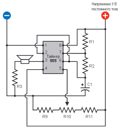 Figure. 6. conclusion "control voltage (output 5) is rarely used, but may be useful. Changing the voltage on it, you can adjust the frequency of the 555 timer. This scheme gives you the opportunity to test the use of this output. The values of the components: the resistor R1 is the resistance 1 KOhm; R2 is a resistor with resistance 10 kohm; -resistor with resistance 100 ohms; R9, R11-resistors with resistance 1 KOhm; R10-potentiometer with linear characteristic and resistance 100 kΩ; C1-0.0047 µF capacitor
The main advantage of using 5 to adjust the frequency output is that you can remotely manage. Connect the output (output 3) another operating in avtokolebatelnom mode, the 555 timer, but it generates a lower rate through a resistor with resistance 2.2 kohm concluded 5 first timer. In this case, you get the effect of sirens, generating DTMF signal when a timer controls the other. If between 5 output and earth you additionally add still and capacitor 100 µF, charge and discharge the capacitor to change the frequency of the sound will be smoother.
Chip connection in the circuit
Generally speaking, the microchips are designed in such a way that they can interact with each other. In this regard, 555 timer cannot be easier to come up with anything, because:
- 3 output, this output of one 555 timer, which can be connected directly to the conclusion 2 (start) the second similar timer;
- output power chip can be sufficient to ensure the appropriate supply voltage output 8 other 555 timer chips;
- the output is suitable for signal or control supply voltage to other types of chips.
On Figure. 7 showing these options.
 Figure. 7. Three ways to connect a timer 555 chip. IC chip output 1 can be: the power source for the second timer, change the voltage on its output "control voltage or activate the withdrawal start
You can connect two 555 timer circuit, which is already installed on your layout fee. On Figure. 8 shows how to perform a joint connecting two schemes that were given earlier in Figure. 5 and 2. Route the wire from the 3 output (output) of the first chip found 8 (power output) of the second and disconnect the existing wire attached to this same conclusion 8. The new wire color diagram shows red. Now after clicking run first its chip S1 output will become the source of power for the second chip.
 Figure. 8. you can combine two schemas, which are shown in Figure 1. 5 and 2, simply unplugging the wire that feeds voltage to the output of the 8 second timer and setting another instead, connecting this conclusion with the release of the first timer (the wire on a color image is shown in red)
You can also use the output of one chip to start another (IE. you can connect the output of the first 3 chip found 2 second). When the signal at the output of the first chip is low, it will be less than half of the Volta. This is significantly below the threshold voltage that is required to run the second chip. Why would you want to do so? Yes, you might want to both timer worked in odnovibratora mode (monostabilnom), at the end of the first high-level pulse chip (negative changes) triggered the formation of a high-level pulse second chip. In fact, this way you can connect to a single daisy-chain as many timers as you want; the latest chip will run first, and they will all be consistently include LEDs, as on a Christmas tree. On Figure. 9 demonstrates how can be connected in this way four timer by spatial location where they will occupy a minimum area (and will be connected by hinged wire installation on a perforated Board and not on the Board of this kind, as our Breadboard). Each pin chip, labeled corresponding numbers from 1 to 4, has enough power to connect them up to 10 LEDs, if you use the load resistors with a relatively large resistance to limit their current.
 Figure. 9. Four 555 timer can be joined into a single daisy-chain, forcing flashing four groups of LEDs, like lights on a Christmas tree or advertising cinema.
By the way, you can reduce the number of chips by using two chips, the 556 timer 555 timers instead of four. Each chip contains a pair of 556 timer 555 timers in one case. But since you have to make the same number of external connections (without connection of supply voltage), I wouldn't worry about this option.
In addition, you can even use timer 558, which contains four 555 timer circuits that will work in avtokolebatelnom mode. However, I decided not to use this chip, because it outputs behave somewhat differently than in conventional 555 timer. But you can still purchase timer 558 and "play" with it as you wish. It is ideal for making "chains of four timers, which I proposed earlier. Reference sheets of technical documentation that possibility.
Finally, returning back to the idea of changing the frequency of 555 timer operating in avtokolebatelnom mode, you can perform the schema of the two timers, as shown in Figure. 10. The wire that connects the chip output IC1 (output 3) and output control voltage (output 5) chip IC2, shown in red. Schematic of the first timer is changed to avtokolebatelnyj mode and it generates the output pulses with a frequency of approximately 4 Hz. To give you a visual confirmation that a occurs in the scheme, this signal is connected the led D1 continue using signal wires through the resistor R7 is served on the control voltage output the second timer.
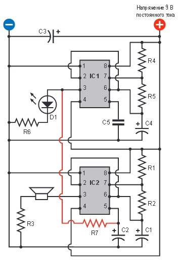 Figure. 10. When both timer are in avtokolebatelnom mode, but the oscillation frequency microchips IS1 IS2 are much smaller than, the output IS1 (3) can be used for modulating sound generated by a second chip IS2. It should be borne in mind that this is a major change compared with the previous scheme, so a few of its components had to change designations. To avoid mistakes, you can dismantle the old schema with your layout Board and perform a new version of this sketch. Try the following denominations initially components: R1, R4, R6, R7-resistors with resistance 1 KOhm; R2 — resistors with resistance 10 kohm; R3 is a resistor with resistance 100 ohms; C1 0.047 µF capacitor is; C2, C3-capacity 100 µF capacitors; C4-68 µF capacitor; C5 — 0.1 µF capacitor.
Capacitor C2 is a capacitor with large capacity, which required considerable time to charge, exercised through resistor R7. While it is a charge, the voltage at pin 5 slowly increases, so the tone generated by the chip IC2, gradually increases. Then, IC1 chip reaches the end of its cycle and switches itself to the point where the capacitor C2 is discharged and the sound signal generation chip IC2 again stops.
You can customize the schema to create all types of audio signals with much greater control over what is done when using programmable single transitional transistor that can perform the same function. Now you can try several options for modifying the schema.
- Increase or reduce by half half the capacity of the capacitor C2.
- Completely disregard capacitor C2 and experiment with changing the resistance of the resistor R7.
- Replace resistor R7 on potentiometer 10 kΩ resistance.
- Change the capacitance of the capacitor C4 to increase or decrease the cycle time chip IC1.
- Reduce the resistance of the resistor R5 twice while doubling the capacity of the capacitor C4. This will cause the frequency of IC1 chips remains roughly the same, but the duration of the high-level signal is much greater compared to the duration of low level signal.
- Change the supply voltage is the voltage to push 9 instead of 6 v or 12 v.
Remember that you can not disable the timer 555, performing voltage changes within that range. You only need to be sure that the negative terminal of the power supply (ground) is connected to the conclusion 1 timer chip and positive — concluded 8.
Author: Charles Platt