The article presents the description of the device, which allows visually by two led lines display the current value of the mains voltage ~220 V and the current consumption in the monitored line, and also provide an audible alarm when the output levels of voltage and current of bounds.
Идея контролировать состояние домашней питающей сети возникает, думаю, у многих, особенно после очередной оплаты за потребленную электроэнергию. Диву даешся, как можно было столько «накрутить», а реальных средств контроля в квартире нет. Устанавливать полноценные электроизмерительные приборы в прихожей как-то неприятно. Кроме того, отображение информации на них не является настолько наглядным, как, например, на светодиодной линейке. Вторая задача, поставленная при разработке этого устройства, – это сигнализация о предельных значениях параметров питающей сети. Кроме того, опыт использования заводских «отсекателей», которые автоматически отключают потребителя при выходе напряжения сети за установленные границы, показал недопустимость их использования при частых и непродолжительных скачках сетевого напряжения. Поэтому, имея опыт программирования микроконтроллеров, автор разработал и изготовил устройство, позволяющее с наименьшими затратами и при минимальном вмешательстве в проводку реализовать следующие функции:
- control and visual led display of the voltage level of the mains;
- control visual led level indication of the current consumed from the network.
- audible output level of the network voltage or current of bounds.
A circuit diagram of the device shown in Fig.1. The basis of the device – a low-cost microcontroller (MCU) DD1 type PIC16F676. It is connected to two led bars HL1-HL12 to indicate the level of current in the network and HL13-HL18 to indicate the level of the mains voltage. The LEDs in the lines connected by the multiplexing scheme by Charlie Allen.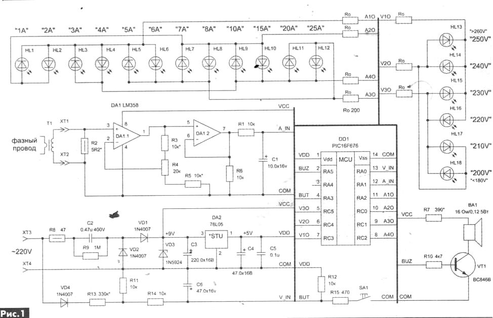 Measurement of voltage and current by using the built-in IC PIC16F676 10-bit ADC. Mains voltage through half-wave rectifier diode VD4 is supplied to the input divider and filter R13R11 R14C6. Current measurement in the network is implemented using a homemade current transformer T1. The signal from the secondary winding of the current transformer is loaded by a resistor R2, is fed to the inverting input of the operational amplifier DA1.1. It is used for amplification and rectification of the input sine wave. Then the rectified signal is applied to repeater DA1.2 and filter the chain of R1C1. The rectified and normalized signal levels of voltage and current are fed to the inputs RA0 and RA1 MC.
Food MK 220 V without a transformer with the ballast capacitor C5. Rectification of the supply voltage is half-wave rectified by the rectifier diodes VD1, VD2. This inefficient scheme is used to keep the total wire power circuits of the measurement. The rectified voltage is applied to parametric stabilizer VD3, C3, providing 9 volts to power operational amplifiers, which comes also on the integral stabilizer DA2 with filter capacitors C4 and C5 to obtain 5 V (power microcontroller).
The device comprises a buzzer on the elements BA1, VT1, R7, R10 and button SA1 with strapping R12, R15, the purpose of which will be discussed below.
The device operates as follows. After power-up the MC is initialized, and submission of short beeps. Dynamic display is performed in a cycle of interruption of the timer t0. The refresh rate of the led lines is 83,3 Hz, which provides good perception. Then every half a second measured voltage and current, comparing them with the constants and setting the flags corresponding to the required inclusion of led strips.
If the measurement result exceeds the specified constants the critical values of voltage or current, then turn on buzzer 2 kHz. For better perception the signal is made intermittent. The frequency of the modulation signal is 4 Hz. The alarm continues as long as the voltages/current are not normalized. By pressing the SB1 button, you can disable the alarm. Pressing the button SB1 or the resetting of the MC will lead to the restoration of the chime.
To measure the levels of voltage and current in the process of setting up the device is included in the program service mode. To enter, be sure to include up the unit while pressing the button SB1. In this mode, the led bars in the binary code and displays the result of measurement in the following way. 8-bit result of the voltage measurement is displayed on the LEDs HL1, HL2, HL13 - HL18, while HL18 corresponds to bit 0, HL13 – bit 5, HL1 – bit 6, HL2 – bit 7 byte of the result. 10-bit result of the current measurement is displayed on the LEDs HL3 - HL12, while HL3 corresponds to bit 0, and HL10 – bit 7 low byte of result, and HL11, HL12 respectively, the bits 0 and 1 most significant byte of the result. The lit led corresponds to the log. "1" and extinguished – log. "0".
The design and details
With the exception of the current transformer all the elements of the device assembled on a printed circuit Board from a unilateral foil fiberglass dimensions 71х34 mm. the PCB Drawing is shown in Fig.2, the items from the PCB – Fig.3, and from the installation in Fig.4. It should be noted that the SB1 and the led lines are sealed from the circuit Board to fix the Board to the front panel.
The design uses round LEDs with a diameter of 3 mm. For clarity of display it is recommended to use LEDs of different colors. The author used three types of LEDs: HL1 - HL4, HL18 – green, HL5 - HL8, HL14 - HL17 – orange and HL9 - HL13 – red.
Resistors SMD was used to those sizes that were available: 1206 and 0805.
Buzzer taken from a faulty Chinese clock. Special requirements for used radiocomponents not shown.
As a current transformer was used small power transformer with a capacity of approximately 1 W from the Chinese radio, which burned the primary winding. The burnt coil was removed and in its place is one incomplete round of phase wires. The secondary winding of the transformer, the passport has the options of 3 V, 300 mA, was used without modification.
Assembly and commissioning
It is recommended to assemble the device in stages with the verification of the operation of each functional unit. First collect the power-supply circuit +9 V and +5 V. Further seal the elements of the measuring circuits and check the voltage coming to the conclusions 12 and 13 MK, which should not exceed 3. Then set all other elements except for resistors R2 and R7. Pre-stitched MK is inserted into the panel and temporarily connect the resistor R7 of the specified value and include the device in the network. If the device does not start and the beeper is making clicking, then it is necessary to increase the resistance of the resistor R7 and to achieve normal device startup if the minimum value of the mains voltage. With the successful launch of MK, the beeper emits a three-tone signal, and the led line voltage indicator should illuminate at least the led HL18.
For adjustment of the measuring circuits of the device will need Latr, as well as the ability to create and measure the required maximum controllable current in a load. Exclusively design method, unfortunately, is not enough, as much depends on the parameters of the current transformer, the transfer characteristics can be very precisely nonlinear at high currents.
Adjustment of the voltage channel is quite simple. The values of the elements of the divider R11R13 can be left as shown in the diagram. By connecting the device to Latro and entering the service mode, record the displayed LEDs in binary format the measurement result of the voltage at the test points: 180 (lower allowable voltage limit of the network), 200, 210, 220, 230, 240, 250, 260 (upper permissible limit of the supply voltage). You then transfer the measurement results to hexadecimal, for example, using Windows calculator and make these constants in the first 8 cells of the EEPROM of the controller (or put them in a table located at the end of the file "220_indr.h", and recompile the program).
Для наладки канала измерения тока сначала следует подобрать сопротивление нагрузочного резистора R2. Это делают независимо от схемы устройства. При максимальном контролируемом токе в первичной обмотке ток, протекающий во вторичной обмотке трансформатора, при этом падение напряжения на резисторе R2 должно находится в пределах 0,5…0,8 В. Если добиться таких параметров не удастся, то следует перемотать вторичную обмотку более толстым проводом или же смотать имеющуюся обмотку и намотать ее тем же проводом, но сложенным вдвое-втрое.
После чего трансформатор тока подключают к схеме. Следующей задачей является настройка коэффициента усиления ОУ DA1.1 подстроечным резистором R4. При этом МК в панельку не устанавливают, а выходное напряжение усилителя контролируют на выводе 12 МК цифровым вольтметром. Подключив питание устройства и пропустив через токовую обмотку Т! максимальный тока, добиваются получения в контролируемой точке напряжения 2,5…3 В.
Determination and recording in the MK constants corresponding to levels of current in the ignition once the led current line-up, produced using service mode on the previously described methodology. There are a total of 13 current constants: 12 corresponding to the ignition 12 LEDs line and the 13th – the ultimate sound of the alarm. Current constants are written in the EEPROM cells immediately after the constant voltage, and first comes the high byte constant that can take values from 00 to 03, and then the low byte. The author has used the following number of displayed currents: 1, 2, 3, 4, 5, 6, 7, 8, 9, 10, 15, 20, 25 and audible alarm when you reach a current of 30 A.
It should be noted that the device is electrically connected to the network, so if the adjustment is necessary to comply with safety requirements and to feed through an isolating transformer.
Source: Radioamator №7-8, 2014
Author: Dmitry Karelov, Krivoy Rog.