To repair and adjust the various radio receiving and transmitting apparatus is convenient to use an active external probe, equipped with an amplitude detector.
To minimize the impact of the probe on the circuit controlled it must have a high input impedance and low input capacitance.
In Fig.1 is a schematic diagram of an active probe with an amplitude detector, designed for operation with a sound probe, collected in the publication [1], it can also be used in conjunction with other similar devices. Input device voltage high frequency high voltage across dividing capacitor C1, the protective resistors R3, R4 and separating the Sz condenser arrives at the output shutter of the high-frequency field-effect transistor VT1. Resistors R1, R2 is needed to discharge the capacitor C1, which when working with high voltage circuits, for example, in a tube radio can be charged to a voltage of several hundred volts. Counter-consistently included the Zener diodes VD1, VD2 and silicon diodes VD3, VD4 diodes limit the maximum amplitude of the input signal to the gate of VT1 to 5 V. the Diodes VD3, VD4 are also installed to reduce the input capacitance of the probe.
A field-effect transistor amplifies the incoming on its gate the signal voltage of 3.5 times. The amplified signal from the drain through the isolation capacitor C6 is supplied to the amplitude detector made on high-frequency germanium diodes VD5, VD6. In the presence of the input RF signal, capacitor C7 is charged so that the voltage at its point of connection with VD5 is negative relative to the common wire. This voltage via a high resistance resistor R5 is supplied to the gate of VT1. The greater the amplitude of the input voltage, the more negative the voltage on C7, the more closed the transistor VT1. Thus, the automatic gain control stage transistor VT1, which improves the usability of the device.
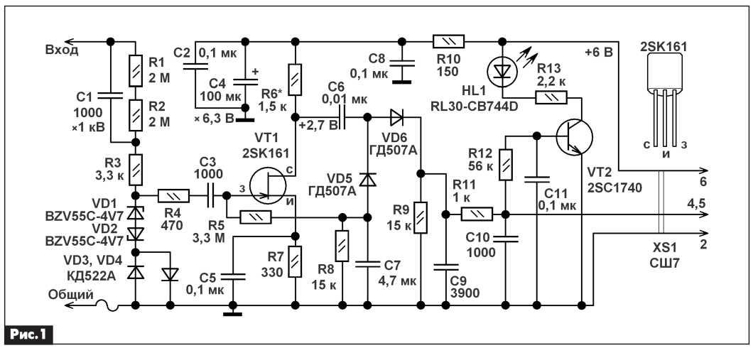 Продетектированный сигнал модулирующей низкой частоты выделяется на конденсаторе С9. Резистор R9 – нагрузка диодного детектора. Далее, через фильтр R11C10 он поступает на вход звукового пробника, к которому подключен выносной щуп. К выходу диодного детектора также подключен усилительный каскад на транзисторе VT2. При наличии на входе устройства высокочастотного сигнала амплитудой более 100 мВ, транзистор VT2 открывается, начинает светиться светодиод HL1.
Led indication when the input high-frequency signal is convenient because it is possible to detect the presence nemogu - mirovnog RF signal at the input device, for example, the presence of high-frequency self-excitation at the output of the power amplifier of audio frequency, voltage, etc. devices.
The amplifier stage is powered probe voltage of +6 VDC through the filter R10С2С4С8. The device consumes about 1.5 mA.
Максимальное входное напряжение (в зависимости от входной частоты) 30…250 В. При этом, чем больше частота входного высокочастотного сигнала, тем меньше максимальное входное напряжение. При значительной перегрузке, например, если вы подключили щуп к передающей антенне 27 МГц, где ВЧ напряжение может достигать сотен вольт, резистор R3 перегорит. Работа щупа испытана на частотах до 60 МГц, при частоте входного сигнала ниже 10 кГц или выше 30 МГц чувствительность щупа снижается. Расширить рабочий частотный диапазон щупа до 50…100 МГц можно, если резисторы R3, R6 установить меньшего номинала, а резистор R7 и конденсатор С5 заменить перемычной. При этом значительно возрастёт потребляемый устройством ток, а максимальное входное допустимое напряжение при работе устройства на частотах выше 5 МГцумень- шится до 5 В.
The design and details
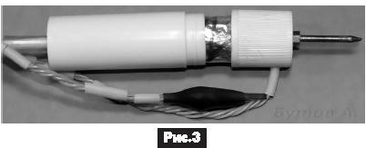
All parts are mounted on a small circuit Board (Fig.2). After the health check and debug the device, circuit Board wrapped wide adhesive tape "Scotch", over which is wound an electric screen, self-adhesive, aluminum foil, electrically connected to the common wire. Contact wire attached to the foil with tape, after which the circuit Board is placed in a round case of the glue stick (Fig.Z).
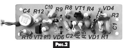
Resistors can use any type of small, for example, C1-4, MLT, C1-14. Most of the resistors are installed vertically. The C4 capacitor type K53-19, K53-30 or imported counterpart. We import tantalum capacitors in cylindrical housings dark stripe marked negative terminal, a rectangular surface mounting a strip marked positive conclusion. The remaining ceramic capacitors, for example, K10-17, K10-50, or equivalents. The capacitor C2 must be installed in the vicinity of the respective terminals of resistors R6 and R7. For convenience of installation, some resistors and ceramic capacitors used in the SMD version.
Стабилитроны BZV-55C4V7 можно заменить BZV55C-5V1, BZV55C-5V6, BZV55C-6V2 и другими аналогичными маломощными на напряжение стабилизации 4,7…6,2 В с возможно меньшей ёмкостью перехода.
KD522A diodes can be replaced by any of the series KD503, KD510, KD512, KD521, 1 N4148, 1N914, 1SS244. Instead of germanium diodes can be used gd507a 1d507a or more high 1d402a-B, GD402A-B. Led RL30-CB744D surharge blue glow, you can replace RL30-GH744D. A low noise high frequency field effect transistor 2SK161 can be replaced by any of the series KP307, 2P307. Suitable instance with a voltage cutoff of no more than 3 V. the Transistor 2SC1740 you can replace any of the series SS9014, SS9013, ВС547, 2SC1815, КТ3102, КТ6111. Suitable instance of the transistor current transfer ratio base of at least 250.
Налаживание устройства заключается в подборе номинала резистора R6 таким образом, чтобы на выводе стока VT1 было напряжение 2,5…3 В. Если при этом номинал резистора R6 получается больше 2,2 кОм, то следует установить резистор R7 меньшего номинала и повторить настройку. Выносной щуп с амплитудным детектором подключают к звуковому пробнику с помощью штекера CШ-7 и трёхжильного экранированного провода. Внешний вид устройства в сборе, подключенного к звуковому пробнику, показан на фото в начале статьи.
Literature
- Бутов A. Л. Миниатюрный звуковой пробник с сетевым питанием // Радиоаматор. – 2009. – №9. – С. 2-4.
Author: Andrey Butov, S. Kurba, Yaroslavl region.
Source: Radioamator No. 4, 2014