Chip is an amplifier of low frequency with a nominal power output of 4.5 W into 4 Ohms. Intended for use in paths NCH household radio.
Body type 201.12-1 or 238.12-1. Weight not more than 2 and 2.5 g, respectively.
Pinouts: 1 — power (+ Un); 4 — volkodavova, food (+Un); 5—correction; 6—feedback; 7—filter; 8—air inlet; 9— General (Un); 10—emitter output stage; 12.


The electrical parameters of the chip

Limit operational data for chips
Напряжение питания – 18В *.
Максимальное амплитудное значение входного напряжения – 2 В.
Максимальное амплитудное значение тока в нагрузке – 1,8 А.
Permissible DC voltage:
на выводе 7, не более – 15 В,
на выводе 8 —0,3 … +2 В.
Максимальная рассеиваемая мощность – 0,5 Вт **.
Температура окружающей среды -10 … +60° С ***.
Notes:
* Action time up to 3 min
** Without heatsink.
*** At T> +25 ° C dissipated power, W, is calculated by the formula:

 The dependence of the output voltage from the supply voltage when RL =4 Ω, K, — 10%,
T= + 25° C. the Shaded area of the spread of values of the parameter for 95% of the chips. The solid line shows the typical dependence
 Frequency response
 The dependence of the harmonics of the power output
 The dependence of the harmonic frequency
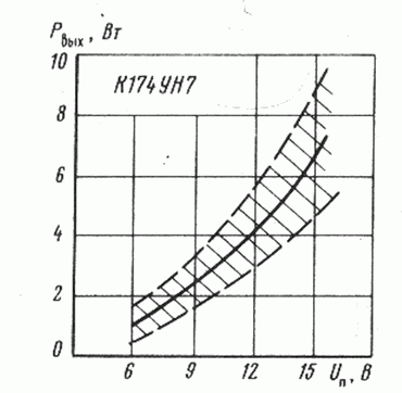 The output power versus supply voltage with RL = 4 0 m, Kr = 10%, T= 25 C. the Shaded area of the spread of values of parameters for 95% of the chips. The solid line shows the model dependence.
Schemes of inclusion
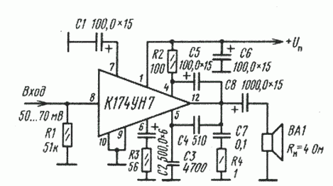 Typical connection diagram of the chip К174УН7.

Schematic diagram of the bridge amplifier of low frequency for two chips К174УН7.

Schematic diagram of the generator of the erase and bias tape on the chip К174УН7.
Additional references:
- Improving the quality of the sound // Radio-1984.—№ 11.— P. 58.
- Filin S. Reducing distortion in power amplifiers on the IC. Radio.-1981 — No. 12.— P. 40.
- Nazarov V., HF receiver on IC series К174 II Radio,— 1981,—№ 3.—S. 27— 29.
- Nazarov V. VHF receiver on-chip and Radio,-1982,- № 7,— Pp. 29, 30.
- Two amplifier circuits. Radio,-1980, No. 9.— P. 58.
- Integrated circuits series К174: Directory.— M.: Central research Institute "electronics", 1981, vol. 1.— 68 p