The proposed digital voltampermetr (hereinafter referred to as the device) is designed for laboratory power supply unit (hereinafter LBP) and is designed for DC voltage and current within user-definable, and also load power consumption. The device provides two types of protection: output voltage from exceeding the LBP and from exceeding the allowed output current timogo.
When the protection device disconnects from the network, and delivers LBP jerky sound signals of different, depending on the cause, tonality. It can be returned to operational status in two ways: manually, by pressing a button or automatically after elimination in ranks that caused the trigger to defend you. The device is based on micro controller PIC16F876-20I/SP [1] and is equipped with LCD that displays two lines on the screen to 16 characters.
Main technical characteristics
Tension measurement limit tion UP (from step 1) ... ... ... ... ... 5-61
Limit current measurement (I)P (in increments of 1 (a)), and ... ... ... ... ... ... ... ... ... ... 2-21
Voltage protection thresholds (from step 1) ... ... ... 1-UP
the current (1 a) ... ... ... ... ... ... ... ... ... ... ... ... ... ... ... ... 1-IP
Maximum measured power, w ... ... ... ... ... ... ... ... ... 1280
Number of measured gradation ND voltage or current from 0 to set Pres Affairs dimension ... 1024
The number of decimal digits after the decimal point in the conclusions of the IOM on indicator of the importance Sri voltage ... ... ... 2
The number of decimal digits after the decimal point in the conclusions of the IOM at the indicator value current Research Institute
<10 А……………………………………………………………………………………. 2
≥10 А…………………………………………………………………………………….. 1
Discreteness display power, W ... ... ... ... ... ... ... ... ... ... ... ... ... ... ... .... 0.1
Power on the screen when the Bora, especially when more than 9.99 and may differ slightly from the works he displayed values of current and voltage. The fact of the matter is that to calculate the power pro gram device uses more than a waypoint, not rounded before displaying the values of these parameters.
Connection diagram nodes and blocks the device depicted on Fig. 1. LBP is connected to the mains 230 v, ~ 50 Hz through a switch, controlled by a signal to its connector with HR1 explanation open clam HR3 measurement and protection block (BIZ). Supply voltage biz, coming at it from the individual contact block not HT4 shown in the diagram, the power source can be in the range of 10.5 to 30 this sources Nick must remain enabled regardless of the status of the switch.

Figure. 1
HR1 is connected to connector BIZ button, pressing on which the SB1 who rotate the device in working condition after protection and eliminating the causes of the NIA. Button SB2, serving as a layperson to set or change a couple of metres of the device, is connected to connector HR2. With connectors XS1 XS2 and connected LCD HG1 and connector HRZ-mention th above switch and current protection: sound signalling devices 1 and light-emitting diodes HL1 and HL2.
While the values of the measured values are within the permissible limits, BIZ works in measuring mode. LCD screen looks as shown in Figure. 2. All the alarms in this mode is turned off, and the switch post paet signal allowing CE supply network voltage on LBP.

Fig. 2
BIZ continuously measures their voltage, coming on the block ХТ1, and proportional current load resistor voltage NIE Padé RS1. As soon as any of these values exceed permissible value, BIZ goes into protection mode and removes the signal to obtain crucial enabling switch. LBP, lacking power, measures em work.
Return of the protection regime in the working regime, as Reed was already mentioned above, you can manually, press button "SB1, or automatically after tackling congestion causes NIYA. The user must choose in advance one of these options. SB2 button is used to set parameters, which will be described below.
Depending on the cause of the fires at Bani protection behave differently LCD, sounder 1 and FR todiody HL1, HL2. When voltage is exceeded will be included, and in HL1 led the left half of the upper row LCD screen flashing appears the inscription indicating the key pillar exceeding value. The bottom line will be displayed (as in Figure. 3) надпись “ЗАЩИТА ПО НАПР.”. Излучатель звука НА1 станет подавать короткие двухтональные сигналы (8267 и 8346 Гц), повторяющиеся каждую секунду.

Fig. 3
Current overload will include Cheung led HL2, and ashing on the display text from exceeding the current fascination for perfect. The bottom line of the screen as shown in the Figure. 4, будет выведено сообщение “ЗАЩИТА ПО ТОКУ”. Звукоизлучатель НА1 станет подавать короткие двухтональные (8818 и 8661 Гц) сигналы, повторяющиеся каждую секунду.

Fig. 4
The device features a somewhat broader. For example, the control signals led HL1 and HL2, generated by the biz, you can use to either the defence section but current and voltage. If you add an appliance in the switch circuit loading Ki LBP, managed a signal before the assigned led HL2, the load will be disabled when you re loading current, but will continue to work to develop LBP. However, a sudden increase on LBP output voltage (usually due to its malfunction) the unit must be completely shut down the existing switch, connecting the control circuit to clarify youmu HR3 instead led NL1. You can and do not establish any switches, only the indication of overload, while BIZ will still be in protection mode, from which it will have to withdraw.
BIZ concept images for wife Figure. 5. Напряжение питания блока 10,5…30 В, поданное от внешнего источника на контактную колодку ХТ4 и дополнительно сглаженное конденсатором С1, поступает на вход интегрального стабилизатора DА1. Его выходным стабилизированным напряжением 9 В питается сдвоенный ОУ DА2 (использован только один ОУ этой микросхемы). Это же напряжение поступает на вход интегрального стабилизатора DА3. Его выходным напряжением 5 В питают микроконтроллер DD1 и ЖКИ HG1. Кварцевый резонатор ZQ1 и конденсаторы С3 и С5 — частотозадающая цепь тактового генератора микроконтроллера DD1. Резистор R9 поддерживает высокий логический уровень на входе сигнала установки микроконтроллера в исходное состояние.
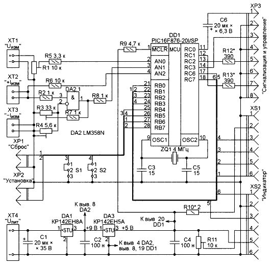
Fig. 5
Power on node screen backlight LCD comes through suppressant resistor R10. By selecting it, you can set the desired brightness. Trimpot R11 fared the best contrast of characters on the screen LCD. R13 R12 and resistors are asking the current through the LEDs NL1 and NL2 (see fig. 1) and can be replaced with jumpers in case use of signals intended for LEDs, to manage the switch. Capacitor C6 is a separation in the circuit zvukoizluchatelja 1 (see fig. 1).
Measured voltage with connector ХТ1 arrives at the trimmer d zistor R1, through which appliance when establishing RA sought rule voltage values, current level at its LCD, testimony exemplary voltmeter. With his engine through the resistor R5 voltage post logon paet ANO internal ADC microcontroller DD1.
The resistor R5 limits to safety without values current through the available at the entrance to ANO microcontroller permanently extended protection diode, if the tension on the engine exceeds the supply voltage of the microcontroller. Especially if the engine accidentally or purposely destroying intentionally set to its highest (on) position.
Obsolete resistor RS1 (see fig. 1) voltage proportional to the load current through the LBP contact decks Ki HT2, HTZ and resistor R2 arrives at the non-inverting input OP AMPS DA 2.1, Wuxi establishing it. The output of the OP AMP is connected to the input of the microcontroller through the resistor R8 AN1, whose role is the same as the resistor R5. Without it, the tension on the inlet of the microcontroller AN1 may exceed its voltage Pete, when current through the resistor RS1 is too large or this resistor is not generally attached to strips HT2 and HT3, and also if you accidentally move the trimmer engines set rezisto ditch R3 and R4 in the invalid provision. These resistors set the amplification factor of the GENERAL CONDITIONS needed to ensure the specified in the program limit of current measurement. Resistor R7 protects the output of the OP AMP circuits with a common wire when installing the engine podstroechnogo resistor R3 in the leftmost position of the scheme.
To the device showed voltage in a load, actually measuring it at the exit of the LBP, the correction was introduced in the following. Help with special voltage not em RS1 input only OU DA 2.1, but also through a resistor R6 on entrance AN2 ADC microcontroller. Program vychita em this tension from what BL but at the exit of the LBP, and this importance, represents the tension on load, LCD displays on the screen.
Signal levels on the outputs of the RC1-RC3 microcontroller, depending on the voltage to AN0 AN1 and entrances and jumpers S1 and S2 are shown in table. Manipulation of jumpers S1 and S2 to specify the desired asset Nye logical signals governing management switches. It gives the freedom to choose the direction of Paul kommuti governing elements. For example, you can use a normally closed or normally open relay contacts, without resorting to the use of additional elements of solid-state invertirujushhih control signals.
Current consumed by BOOZE when not under kljuchjonnyh to connector HR3 izluchatele switch sound and light-emitting diodes are not pre exceeds 32 Ma. If these items under kljucheny, current depends on their condition, increasing the sum of the values for each of the trebljaemogo current. Mack maximum absorbed current is 60 Ma.
| Log. outlet level RC1 | ||
| Position S1 | in theAN0 | |
| Below threshold | Above threshold | |
| 1-2 | High | Low |
| 2-3 | Low | High |
| Log. outlet level RC2 | ||
| Position S2 | in theAN1 | |
| Below threshold | Above threshold | |
| 1-2 | High | Low |
| 2-3 | Low | High |
| Log. outlet level RFROM3 | ||
| in theAN0 | in theAN1 | |
| Below threshold | Above threshold | |
| Below threshold | Low | High |
| Above threshold | High | High |
The concept of the switch is Figure. 6. Control voltage of about 5 in received on its connector HR1 through led indicator that serves as the HL1 commands from the kryvanija switch and resistor filed on radiating diode simistornogo optocoupler U1. This opens the fotosimistor optocoupler, followed by open and TRIAC VS1. He United all contact pads ХТ1 and HT2, poda Vai the supply voltage-230 in the LBP.
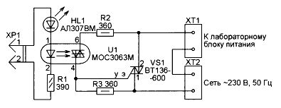
Fig. 6
The design and details
The device used LCD QAPASS1602A with white characters and blue backlit screen. Good and any other alpha-numeric LCD based on HD44780 controller, have the next two lines of 16 characters. Such indicators can have different size and location of the findings to navigate must be overlaid on the charge indicator letter stamps did. Output to screen letters generated by the program, so you can apply those LCD in znakogeneratorah where there are no Cyrillic characters.
Buttons (SB1 and SB2 (see fig. 1) — any suitable for installation on PE rednej. 1 Zvukoizluchatel-dynamic head with active resistance not less than 8 Ohms from the phone. For electromagnetic emitter and comes from Electromechanical alarm clock or phone blasting.
Current sensor RS1 is self-made. This stretch of nichrome wire diameter of 1.2 mm and a length of 20 mm. Its design is 0.02 Ohm resistance. Special precision is not required, since the unit still need to Ku calibration impos Not worth the use wire of smaller diameter, because the pain of current it will notably become very hot. It should be borne in mind that the length of a segment of wire should be a little pain she specified that its ends can be inserted into sockets contact pads HT2 and HT3 and clamp screws there. The current length is measured between the points of the clip.
Источник напряжения, подаваемого на колодку ХТ4 БИЗ, — доработанное зарядное устройство “Delta” 5 В, 0,4 А для сотового телефона. Все детали во вторичной цепи установленного в нём импульсного трансформатора и связанные с ними печатные проводники удалены. На освободившемся месте в новые отверстия вставлены выводы четырёх диодов КД212А, образующих выпрямительный мост, а вместо сглаживающего конденсатора 470 мкФ на 10 В установлен конденсатор такой же ёмкости с номинальным напряжением 16 В. Соединения выполнены выводами деталей и отрезками монтажного провода. В сетевом выпрямителе зарядного устройства сглаживающий конденсатор 3,3 мкФ на 400 В заменён конденсатором на такое же напряжение, но ёмкостью 5,6 мкФ.
After re delki charger its output voltage ever proposal Elk up to 12.7 in, with high koomnyh heads tional phones connected to the exit, barely y Shen low frequency rumble. When connecting to a voltage drops to 10.5 BIZ and TRANS formator slightly warm.
All the parts BIZ posted on the printed circuit board from one side of foil-clad fiberglass Tol anniversary 1.5 mm (Figure. 7) с такими же размерами (80×36 мм) и расположением крепёжных отверстий, что и плата ЖКИ. Это даёт возможность установить эти платы одну над другой на пустотелых втулках высотой 10… 12 мм и соединить их четырьмя винтами М2,5 с гайками.
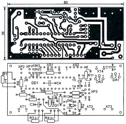
Fig. 7
DD1 microcontroller on the motherboard should be a Panel, where it is already inserted grammirovannym request. Number 20 after de FISA PIC16F876 microcontroller in the title-20I/SP means his Pres detailed frequency in megahertz. Because BIZ applied ZQ1 Quartz resonator 4 Mhz frequency, with suitable options for microcontroller and a lower frequency, up to 4 Mhz. Can be no schema changes, pro gram and printed circuit board using microcontroller PIC16F876A-I/SP. Since all its variants are able to operate at up to 20 Mhz, it is not listed in the title.
It is possible to replace any of these latter above microcontrollers on Ana logical in housing for surface mounting (with index EO after fractional features in the title). But this will require the use of a special adapter for mounting on printed circuit board or its complete redesign.
Integrated stabilizer CD 142 EN8A can be substituted for or similar on 7809 +9 and CD EN5A 142 — on the 7805 voltage or the other hundred established +5 b. To not precisely cost of corporate takeovers, stabilizers, chosen as replacements should be the 220 sugar case.
Capacitors C1 and C6-niobium oxide to 53-19, remaining capacitors satory-ceramic. Adjustable resistors R1, R3 and R4 - many revolving series 3296W, and R11-RM065. Permanent-MLT resistors or similar in the diagram specified wattage. All domestic Resi story and capacitors can replace imported.
Pad ХТ1-HT4-Nye dvuhkontakt screw DG301-5.0-02 in increments of 5 mm and findings to the limit current of 16 a. If the device assumes the former pluatirovat with more current, to boats should be replaced by a more powerful.
Connectors HR1 and HR2-PLS-2 and HR3-PLD-8. As a PIN pad for S1 and S2 jumper settings (jumper MJ) used PLD-connector 6. XS1 XS2 and connectors-PLD-6 and the second part for them is the PLX-6R (angle to reduce the height of Mont supervision).
Коммутатор собран на отдельной печатной плате из фольгированного с одной стороны текстолита толщиной 1,5 мм и размерами 35×25 мм, изображённой на Figure. 8. TRIAC optocoupler U1 MOE 3063 m [2] has a built-in transition detection node values voltage switched leg instant noodles provisions through zero. This allows you to open op the TRIAC x/E1 at the Momen you that significantly reduces switching noise. Direct replacement us optocoupler MOE 3063 m-MOS 3043 m and the MIM 3083 m. They have current emitting diode IFT, необходимый для гарантированного открывания фотосимистора, лежит в интервале 3…5 мА.
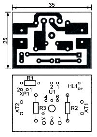
Fig. 8
Similar optronam MOE 3041 m MOS3061M and MOOS 3081 m for p tion requires a current of 15 Ma, and MOE 3042 m, ISO 3062 m and ISO 3082 m = 10 Ma. Replacing MOC3063M one of them, it is necessary to pick up R1 such that the current through the emitting diode was not less than (I)FT used optocoupler.
Maximum power, kommuti projected TRIAC BT136-600 without TEP lootvoda — 150 Watts. Setting the TRIAC to the heatsink, the place for which the Board provides you took it to enable 800 Watts. When installing Al BM 307 other LEDs you want to pick up R1 such that current control circuit remained the same. Contact pads ХТ1 and new DG301 propeller-HT2-5, 0-02, HR1-PLS-2. All resistors-MLT.
If you use a different switch designs, it is important that it was connected to the control circuit is not connected with switched circuit and control current does not exceed 25 Ma, allowed timyh to exit the microcontroller.
The establishment of the device
When you first power on BIZ will be set following parameters: limit value measurement provisions of UP — 35 in the current measurement limit (I)P -10 a, voltage protection threshold is equal to UP, and progress — andP, способ сброса защиты — “АВТОМАТИЧЕСКИ”. Изменить их можно только в рабочем режиме, какие- либо изменения при сработавшей защите невозможны.
To make changes, the duration of selection by pressing the button to strike the emergence of SB2 blinking cursor in the bottom right corner of the screen, and then release the button. The screen is completely tjot the form shown in Figure. 9. Underline cursor will be installed under the highest digit values measurement voltage UP.

Fig. 9
Далее короткие нажатия на кнопку SB2 увеличат UP ступенями по 1 В до 61 В, после чего процесс продолжится, начиная с 5 В и далее по кольцу. Остановившись на требуемом значении Umax, продолжительным нажатием на кнопку переведите курсор под старшую цифру значения предела измерения тока IP – короткими нажатиями на кнопку задайте IP в интервале от 2 до 21 А.
Теперь длинным нажатием на кнопку SB2 до появления мигающего курсора выведите на экран изображение, подобное показанному на рис. 10. Курсор в виде подчёркивания будет находиться под старшей цифрой значения порога срабатывания защиты по напряжению. Короткими нажатиями на кнопку SB2 доведите порог шагами по 1 В до нужного значения в интервале от 1 В до ранее установленного UP.

Fig. 10
Another long press on the button will move the cursor under the older SB2 figure a rendered the threshold for triggering the current protection. Short clicks set vite this threshold with step 1 and from 1 a to the current (I)max.
Then, after a long depression and releasing the button, the screen will become SB2 form shown in Fig. 11 or Figure. 12. Курсор будет находиться в первой позиции нижней строки. Короткими нажатиями на кнопку SB2 можно менять надписи “НАЖАТИЕМ КНОПКИ” и “АВТОМАТИЧЕСКИ” в бесконечном цикле. Оставьте на экране нужный способ сброса защиты и длинным нажатием на кнопку до появления мигающего курсора и последующим её отпусканием переведите прибор в рабочий режим. Если выбран способ сброса “НАЖАТИЕМ КНОПКИ”, то в первой позиции нижней строки экрана будет постоянно находиться “звёздочка”. При способе “АВТОМАТИЧЕСКИ” она отсутствует.

Fig. 11
Все установленные параметры, чтобы не терять их при выключении питания, программа сохраняет в EEPROM микроконтроллера. Учтите, начав описанную выше процедуру их установки, нужно обязательно довести её до конца, поскольку запись в EEPROM происходит только в процессе возвращения в рабочий режим. Если процедура прервана, например, выключением питания, то записи в EEPROM не произойдёт и установку параметров придётся повторить. Можно быстро “пробежать” по всем этапам установки одними длинными нажатиями на кнопку, изменяя только нужные параметры или просто просматривая их.

Fig. 12
После первого включения БИЗ, а также после любого изменения значений параметров UP и IP It is necessary to perform the calibration voltage and current. Voltage calibration spend when off Noah load. Install the engine podstroechnogo resistor R1 in the bottom position of the scheme. Apply for block
ХТ1 от ЛБП напряжение, близкое к UPWhile observing it on exemplary volt meter. Moving the engine custom designed leg of the resistor R1 up until match testimony LCD device and reference of the voltmeter.
Before calibration current install engines rigged resistors R3 and R4 respectively in the right and left according to the scheme provisions. Connect LBP, BIZ, a current sensor RS1 and the load according to the scheme depicted in Fig. 1, and in series with the load switch on model ammeter. By changing the load resistance or the output voltage of the LBP, set of exemplary readings of the ammeter is approximately equal to half of IP. Next, using the trimmer rezis Tori R3 and R4 deliver identical readings and exemplary of the ammeter.
As you use the batteries load incandescent lamp, electron device used or resistor of suitable capacity with a work at at least prjazheniem set UP.
Если выбран способ сброса защиты “АВТОМАТИЧЕСКИ”, после срабатывания защиты прибор ждёт 4 с, отключив ЛБП от сети, в результате чего напряжение на его выходе равно нулю. По истечении этого времени БИЗ возвратится в рабочий режим, измерит напряжение и ток и, поскольку они нулевые, подключит ЛБП к сети. Если теперь значения измеряемых величин превышают допустимые, БИЗ снова на 4 с перейдёт в режим защиты. Так будет продолжаться до устранения причины перегрузки.
При выборе способа “НАЖАТИЕМ КНОПКИ” БУЗ будет оставаться в режиме защиты до нажатия на кнопку SB1. После этого он возвратится в рабочий режим, измерит напряжение и ток и, если они в норме, останется в этом режиме. В противном случае он вновь перейдёт в режим защиты до нажатия на кнопку.
Note that if the current chick dates RS1 contact not connected to s ' signature HT2 and HT3 or in place of the connection broken contact Pro izojdjot false positive protection you're current. But at break in the chain of Resi Stora R6 possibly false use fires at over-voltage protection. If the load current measurement is not required, the negative output should load blowing connect to kolodke HT3 along with negative conclusion of LBP. Current sensor RS1 in this case replace the jumper of the copper wire. After this current and power measurements on the LCD become zero financing.
LITERATURE
- 28/40-Pin 8-BitCMOS FU\SH Microcontrollers. — URL: https://lib.chipdip.ru/059/DOC000059963.pdf (14.03.17).
- 6-Pin DIP Zero-Cross Triac Driver Optocoupler (600 Volt Peak) MOC3061M, MOC3062M, МОС3063М, MOC3162M, MOC3163M. — URL: https://www.fairchildsemi.соm/datasheets/MO/MОpdf (14.03.17).
Download the file to the project (файлы печатных плат в формате Sprint Layout 6.0 и программа микроконтроллер)
Author: G. NUGTEREN, g, Kovrov, Vladimir region
Source: Радио №6/2017
Здравствуйте, уважаемый автор. Огромное спасибо Вам за устройство, которое как никогда пригодилось мне вовремя.
Собрал домашний блок питания с напряжением до 65 вольт и током до 25 ампер. Все Китайские показометры, сами понимаете желают иметь лучше характеристики. И вот здесь помогла Ваша разработка. Я ее повторил без всяких затруднений, но есть ряд вопросов личного характера. Не могли бы Вы переслать по почте исходники программы, для личного пользования. Хочу немного переделать под себя. Если с измерением напряжения вопросов нет, линейность и точность меня устраивает на всем диапазоне, то измерение тока, я хочу разбить на три диапазона- 10,20,30 Ампер. И немного дописать в программе вашей, показания температуры. Не хочется отдельно ставить термометр в коробок. А так все в одном флаконе и ток, и напряжение, и мощность с температурой. С уважением Владимир. Почта. vsapiga@yandex.ru и вторая sapiga.va@ukr.net