Диапазон звуковых частот, который способно воспринимать ухо человека, довольно широк, от 20 до 20000 Гц. Как видно из рис. 1[1], наибольшей чувствительностью человеческий слух обладает на средних частотах – в диапазоне от 2000 до 5000 Гц. А область с 200 до 5000 Гц является самой информативной. При проектировании и изготовлении высококачественных акустических систем особое внимание следует уделять звену, отвечающему за воспроизведение звука в зоне средних частот.
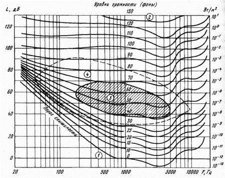 |
| Figure. 1. Frequency characteristic sensations volume: 1-characteristics of the hearing threshold; 2-levels of pain; 3-area speech transmission; scope of musical transmission. |
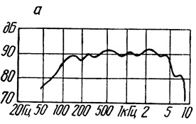
It is known that the most weakest link acoustic systems 35 AU-012 (S-90) their modifications and other similar-MF dynamic 20GDS head-3-8 (the old name of 15A-11A) has sharp decline above 4.5 kHz (fig. 2), and that virtually eliminates the possibility of obtaining high-quality sound reproduction. The second disadvantage is the acoustic quality is about 11.8. And the higher the quality of oscillatory system, the more it underlines the frequency match the resonance, or close to them. That practically eliminates the possibility of a full-fledged non-distorted sound, if not to take the necessary measures. [2].
 |
 |
|
Figure. 2. MF dynamic head 20GDS-1-8 (15GD-11A): a-sound pressure FREQUENCY RESPONSE; b)-dimensions and installation dimensions. |
|
In some editions of 35 AU-1, predecessor, S-90, as MF managers used head 10GD-34 (new name 25GDN-1), is structurally very similar to the head of 20GDS-1-8 (fig. 2, b). Especially widely applied in all versions of S-30, 6AS-2 and other as BASS-MIDRANGE units. It differs from the 20GDS-4-8 the presence of rubber suspension instead of a fabric that weigh down the moving system dynamics and helps reduce its main frequency resonance, as well as softer centrirujushhuju washer to achieve greater progress in diffuser that significantly for LF transducer.
 |
 |
| (a) | b |
|
Figure. 3. MF dynamic 25GDN head-1-8 (10GD-34): a general view; b-the sound pressure FREQUENCY RESPONSE. |
|
To improve the sound quality of dynamic heads 20GDS-1 a. Kiselev, in his article "modernization of dynamic heads 20GDS-1» (radio No. 3, 1999 year, p. 19), proposed to separate between diffuser dust cap and glue it to the favour of the the cone, voice coil edge convex side, i. e. turn it on 180 degrees. If you understand that the author of the article, in fact, equipped the dynamic head optional diffuser that works on the upper frequencies, thus expanded bandwidth, repeatable head 20GDS-1, up to 7 ... 8 kHz. Additional drivers have many broadband loudspeakers. Application of the additional cone which is inserted inside of the diffuser (fig. 5) raises the upper boundary of the frequency range dynamics to 10-12 kHz can be. In this case, at high frequencies the main diffuser stops working due to the relatively flexible, connect it to the voice coil, and the work included a small diffuser, quite hard and easy [3].
 |
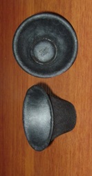
| Figure. 5. Speaker with an additional diffuser. |
Having use of sound system 35 AU-012, decided to enter as well. But instead of the dust cap apply additional high-frequency shout from dynamic 10GDSh head-1-4 (10GD-36 k). Coil inner diameter 10GDSh-1-4 is 25.7 mm and 20GDS head-3-8-25.6 mm. An almost perfect match. The work was carried out as follows.
Soak off dust cap liquid nail polish remover, solvents can be 646, 647, and others. Gently pull his scalpel (fig. 6 a, b). Remember that due to the strong magnetic field system actions on tool steel, deliberate movements, you may damage the speaker elements! Next, wipe with a cotton swab dipped in the same nail polish remover, diffuser from the glue. Coat with glue "moment" the lower part of the voice and the upper part of the voice coil. Dry 10-15 minutes. Again both promazyvaem details and immediately connect them by pushing with some force (fig. 6). Mouthpieces I have were brand new. But can the above way to retrieve them from the old loudspeakers (fig. 6). The same actions hold for 25GDN-1.
Конструкция рупора разработана для динамической головки 10ГДШ-1. Для 20ГДС-3-8 и 25ГДН-1-4 его следует подогнать. Подгонка заключается в поэтапном срезании его края, измеряя, после каждого срезания, АЧХ динамика. Операцию повторяют до тех пор пока не получат наиболее ровную кривую АЧХ в приделах средних частот. Срезав, примерно, 10 мм края рупора проводят измерения. Второе и последующие подрезания следует проводить очень аккуратно, срезая не более 3 – 1 мм (в порядке уменьшения). В итоге, боковая поверхность рупора внутри составила около 7 мм (от пылезащитного элемента колпачка до края обрезки). Обрезку исполняют маникюрными ножницами (рис. 7,б), поскольку они оказались самым приемлемым инструментом для такого вида работы, имеют миниатюрные округленные режущие поверхности. Обрезанный край, для придания жесткости, пропитывается клеем БФ-2, немного разведенным этиловым спиртом.
Измерения АЧХ производят с помощью конденсаторного микрофона (желательно измерительного), размещенного на одной оси с головкой*, в пределах 30 – 40 см, компьютера и программы RightMark 6.2.3. Микрофон подключается к линейному входу звуковой карты компьютера, а динамик к усилителю компьютерных АС. Запускают программу RightMark 6.2.3 и проводят измерения АЧХ звукового давления [4]. Важно, что бы в усилителе регуляторы тембра были в среднем положении, а режим тонокомпенсации и корректирующие звенья отключены. Испытуемая головка размещается наиболее удаленно от стен, мебели и других предметов.
| (a) | 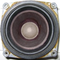 |
 |
| b | 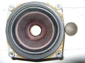 |
|
| In the |  |
 |
| g |  |
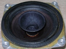 |
| Рис. 6. Приклеивание рупорка на 15ГД-11А: а – головка динамическая 15ГД-11А в оригинальном исполнении; б – головка динамическая 15ГД-11А с извлеченным пылезащитным колпачком; в – головка динамическая широкополосная 10ГДШ-1-4 (10ГД-36К), высокочастотные рупорки; г – головка динамическая 15ГД-11А с рупорком. | ||
| (a) | 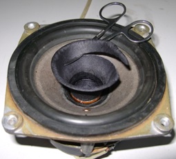 |
| b |  |
| In the | 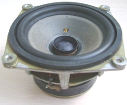 |
| Figure. 7. voice Formation dynamic head 25GDN-1-4: and-cut process; b-measurement of the height of the wall; in-phase completion. | |
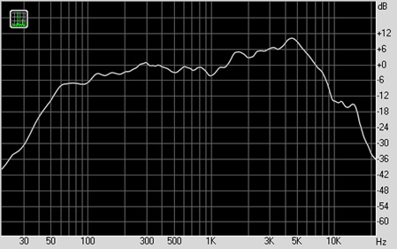
Such refinement has not only made it possible to expand the band played heads 20GDS-4-8 and 25GDN-1-4, up to 10 kHz (fig. 8), but also get rid of structural overtones resulting from the deformation of the dust cap.
| (a) | 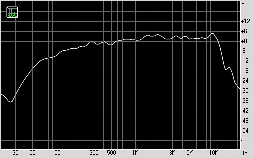 |
| b |  |
| Figure. 8. Amplitulno-frequency characteristics of modified heads: a-20GDS-4-8; b-25GDN-1. | |
To reduce q apply acoustic damping heads using the PAS. Cushioning heads wadding less efficiently and, moreover, contributes to improving the resonance frequency. With a view to enhancing the effectiveness of the PAS on a mobile system that operates in the acoustic design of dempfirujushheju heads, the fabric should be placed as close as possible to the cooling tower. The most rationally arrange PAS in holes diffuzoroderzhatelja. To do this, from the cardboard with a thickness of about 2 mm cut out eight identical elements (fig. 9). The total area of the openings for the head 15GD-11A shall be 22. 28 cm2. One side of each element grease with glue moment. Through 5 minutes of paste on the track, with the help of the hoop for embroidery, cotton fabric. Through 30 minutes of cut fabric around the items. Elements PASS slightly curve and paste in difuzoroderzhatelja window (figure. 9. b). Places sklejki Additionally coat with glue [5]. It is important, what would the fabric in the holes of the elements was tight, otherwise the effect of the application of the PAS will not! Application of PAS, i.e. acoustic damper allows you to delay their own fluctuations as a result of the diffuser will drop significantly "poslezvuchanija" and increase sound quality dynamics.
| (a) |  |
| b |  |
|
Figure. 9. Головка 15ГД-11А: а – элемент ПАС; б – ПАС в окнах диффузородержателя. |
|
Damping effect of PAS to head a dynamic 15 DG-11A graphically represented in Figure 10.
 |
| Figure. 10. Damping effect of PAS to head 15GD-11A. |
Effectiveness of PAS has been tested by the staff of Berd radio factory. In particular, the harmonic coefficients have been measured head 15GD MF-11A with PAS and without a PASS. The results of the measurements shown in table 1, indicate that PAS can significantly reduce harmonics coefficient in the frequency range in which the human ear has the most sensitivity.
Table 1. Harmonic coefficients of head 15GD-11A.
| Frequency, Hz | Harmonics coefficient,% | |
| 250 | 1,5 | 0,6 |
| 400 | 2 | 1,1 |
| 630 | 1,5 | 1,1 |
| 1000 | 1,1 | 1,0 |
| 2000 | 1,5 | 1,2 |
| 4000 | 0,6 | 0,5 |
On the PAS method is recommended for any heads, working in the MID range. And for the LF speaker is in the back of the box, closed and in Windows to operate correctly, fazoinvertornogo [7]. Special calculations for making PAS does not exist. Modern manufacturers of acoustics material density, Windows etc. picked experimentally.
In conclusion, suspensions, heads to restore elasticity, impregnate spray "air conditioning and timing belts.
After such refinement has significantly increased the frequency range of up to 10 kHz (!), improved linearity of the FREQUENCY RESPONSE of the sound pressure and, most importantly, quality surround sound speaker system as a whole.
When measuring FREQUENCY-RESPONSE speakers to the microphone, there are special requirements. It must have a wide frequency range, not already 30-18000 Hz, "smooth" the AFR, the small size of the membrane.
The highest electro-acoustic parameters are condenser microphones, and this is their main advantage compared to other varieties of microphones. Condenser microphone frequency response is distinguished by its flatness. In the range of resonance of the membrane can be very uneven low above the resonance it increases slightly. Due to the low uneven characteristics of condenser microphones are used as measuring. Measuring microphones produce on the frequency range from 20-30 Hz to 30-40 kHz 1 DB uneven frequency 10 kHz and no more than 6 DB more than 10 kHz. This microphone capsule sizes take in range 6-15 mm, because of this it is not sent to the frequency of 20-40 kHz. His sensitivity is equal to or less than-60 DB.
Microphone capsules Panasonic WM61 [8] is ideal for use as a measurement.
Connect the CAP directly via a PC using a microphone, phantom power for it to work, is not recommended, due to the great likelihood of interference and noise, reduced sensitivity, which would have a negative impact on the quality of the measurements. The microphone must be connected to the audio input port of the motherboard through harmonizing link-microphone pre-amplifier.
To make such a device with their own hands (fig. 11) is not difficult. It consists of, placed in a tube with a length of 20 cm, diameter 6 mm, capsule microphone, microphone amplifier OC ORA 2134, with high performance, chemical power supply voltage 9 volt, type "krona".
| (a) | 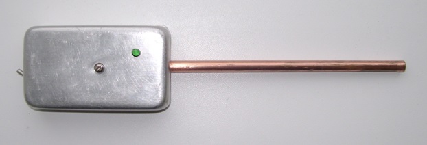 |
| b |  |
| In the | 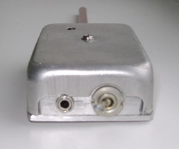 |
| g | 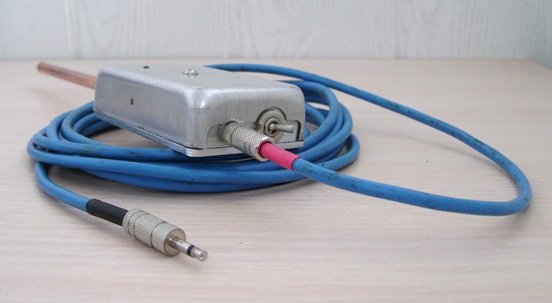 |
| Figure. 11. Microphone measuring: a view from the side of the LEDs; b-view from the side of the CAP; -view from the line-out; g-general view. | |
Schematic electric Schematic of the measuring microphone is taken from the source [9]. After some changes to the looks presented at fig. 12. The capacitor C3 replaced film (k-73 to-78 or other recommended for installation in the signal chain of sound devices). Establishment of the amplifier is reduced to a collection of LEDs, which would decline to 2 volts at the sites specified in the schema.
 |
| Figure. 12. schematic electrical schematic. |
Печатная плата изготавливается из фольгированного стеклотекстолита размерами 55 х 20 мм – рис. 13. Проектирование и печать выполняется на ПК с использование программы Sprint Layout 6.0.
| (a) | 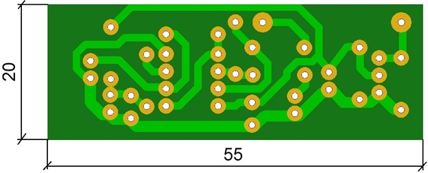 |
| b | 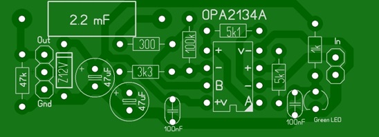 |
| Figure. 13. Pcb: a view from theо стороны дорожек; б – размещения деталей. | |
Все это монтируется в металлический корпус – для экранирования схемы – рис. 14.
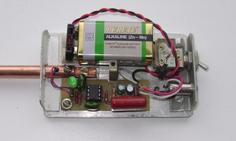 |
| Figure. 14. The layout of elements in the chassis |
Connect the measuring microphone to line-in sound card PC via a shielded cable with two conductors. Screen wire connects on one side-part of the sound card, it also has a positive effect on the accuracy of measurement-fig. 15.
 |
| Figure. 15. Diagram connecting cord. |
This design has a wide range of operating frequencies, a relatively high sensitivity, flat FREQUENCY RESPONSE, "hear" sounds at a greater distance, compared with, for example, FEA-3 microphone. Measurements can be made with almost any audible human ear distance, and this is important when testing not only one head, and the entire acoustic system (s), such as indoors or inside the vehicle. MIC tested successfully with the program Right Mark 6.2.3. Presented in figures 3 and 8 speaker sound pressure FREQUENCY RESPONSE charts built using this program.
Note. In order to eliminate the negative influence of acoustic short circuit on the results of the measurements of the head 20GDS-1-8 and 25GDN-1-4 should be placed in the box with open back wall, outside and inside covered with wadding. Speaker mount on the outside of the front panel. Otherwise the air resonating in the hole under the head, will be a distortion. The graph of the AFR is manifested in the form of peaks and dips.
PCB microphone measuring lay format:
[hidepost]Download[/hidepost]
Literature
- Mazurenko, Y. high-Quality audio equipment. \ M. : Radio and communication, 1993.
- Marchenko V. Revision of the dynamic head 15ГД-11A. Radio, No. 7, 2013.
- Boots M. Acoustics. Textbook for high schools. \ M., "Communication", 1978.
- Марченко В. Доработка динамических головок и измерение их частотных характеристик. \\ Радио, №2, 2014.
- Марченко В. Доработка динамических головок и измерение их частотных характеристик. \\ Радио, №2, 2014.
- Марченко В. Модернизация АС 35АС-012 (S-90). \\ Радио, №8, 2014.
- Молодая Н. Акустическое демпфирование громкоговорителей. \\ Радио, №4, 1969.
- https://dl.dropboxusercontent.com/u/87298597/blog/em06_wm61_a_b_dne.pdf
- http://audiogarret.com.ua/viewtopic.php?f=15&t=7866#p135608]
Author: Vladimir Marchenko, Uman, Ukraine