The article provides an overview of the power amplifiers of sound frequency (umzch) Amateur radio development, positioned as a class amplifiers "Super – А». Статья адресована в основном тем читателям журнала, которые привыкли думать самостоятельно, и обладают достаточной квалификацией. Надеюсь, что приведенная ниже информация окажется для них полезной.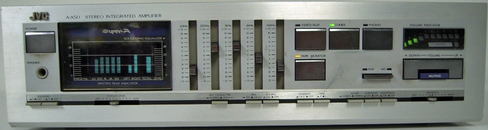
Writing this article prompted attempt resuscitation (preventive maintenance) honored with more than twenty years of experience, amp Bragin sample 1990 [1]. During the works there was a desire to replace used in the amplifier OU modern and collect another copy of this umzch. In the process of doing the task of finding a suitable op-amp, the Internet was discovered a considerable amount of useful information that is relevant to modern developments in amplification devices, and draw appropriate conclusions. Some of them will be briefly described below.
Начнем с краткого описания самой идеи режима «Super – А», а затем обнаруженных в сети проектов (всего лишь 2), являющихся прямым ее продолжением. Еще два УМЗЧ радиолюбительской разработки, вклинившиеся в этот обзор, актуальны и по сей день. Их исходные схемы взяты со страниц журнала «Радио».
Усилия разработчиков транзисторных усилителей давно уже направлены на поиск технических решений, исправляющих присущие им недостатки. В рассматриваемом случае на уменьшение искажений в области нуль-перехода сигнала, характерных для класса АВ, стараясь удержать транзисторы неработающего плеча усилителя от полного запирания путем динамического управления его смещением (так называемый, режим «Super – А» и аналогичные) или создать схемотехническую структуру, сглаживающую начальный, наиболее нелинейный участок ВАХ и биполярных транзисторов. Характерные для режимов «Super – А» и АВ осциллограммы продуктов нелинейности, полученные с выхода измерителя нелинейных искажений, на которые для наглядности наложен исходный синусоидальный сигнал, показаны на Fig.1.

Figure. 1
Применение на выходе УМЗЧ полевых транзисторов, вопреки распространенному мнению, проблему не устраняет: «В момент перехода плеча в неактивное состояние происходит «звон» на индуктивностях конструктива. Поэтому важно обеспечить минимальные длины проводников от полигонов платы до самих транзисторов (в идеале – транзисторы впаяны в плату), безындуктивные эмиттерные резисторы и т.п. Об этом уже многократно говорилось. Поскольку причина возникновения искажений не в транзисторах, то и методы борьбы идентичны. Либо «вылизывание» конструктива, либо недопущение перехода плеча в режим отсечки, а лучше всё вместе [4]».
Изложенное выше, к сожалению, относится не ко всем разработчикам. К примеру, Н. Сухов в своей статье «К вопросу об оценке линейных искажений УМЗЧ» [5] практически прямо заявляет, что он ничего не понял, разницы не услышал, или не заметил и не собирается работать в этом направлении. Его слова «Проведенные автором испытания ряда усилительных устройств с динамическим смещением транзисторов выходного каскада (Super А фирмы JVC, Non Switching фирмы Pioneer, New Class А фирмы Technics) показали, что действие динамического смещения ощутимо только при малых токах покоя выходных каскадов (менее 20…30 мА), а при больших токах оно практически не влияет на линейность усилителя. Другими словами, каскады с динамическим смещением позволяют практически устранить «ступеньку» при токе покоя выходных транзисторов порядка 15…20 мА вместо 50… 100 мА, но в то же время требуют значительного усложнения схемы (наиболее совер шенное усилительное устройство с динамическим смещением – «Super – А» реализуется на 11 транзисторах) и заметно ухудшают термостабильность тока покоя, не изменяя линейность усилителя в режиме номинальной мощности и не улучшая КПД усилителя» однозначно на это указывают.
Moreover, the author did not even bother to inform the reader what the amplifying device, it has been tested. This naturally suggests the idea, based on a number provided by an author they discovered the alleged shortcomings of the solution that under a valid definition of "a number of amplifying devices" is just one [2]. The article is preceded by several publications by the same author called "umzch high fidelity" and therefore the author's position in this matter becomes absolutely clear. The level of this development briefly and well discussed in [6]. In Fact, N. Sukhov his long publication covers the development of circuitry umzch specified Y. Mitrofanov [2]. For this reason, the appearance in 1990 umzch Bragina [1] gone unnoticed. However, this direction of development of Amateur radio still lives. Consider some of the developments in this area.
Umzch project "Natalie"
All of his construction [7] is based on the basis of the amplifier Bragin. Mode "Super-A" itself is missing. Is used instead of the hard stabilization of the residual quiescent current is not active shoulder at the output stage of the amplifier [11]. To trace the history of the creation of this unit is not possible due to the fact that the developer of the project to date has removed almost all the intermediate circuit decision. The project "Natalie" is clearly commercial.
Случайно обнаруженные не окончательные варианты схем этого усилителя выглядят, тем не менее, на первый взгляд более привлекательными, чем некоторые последующие их версии, и вполне работоспособными. В них было использовано весьма оригинальное и интересное решение – оптронное управление коллекторными токами транзисторов выходного каскада, в последствии замещенное относительно тривиальным, но более быстродействующим вариантом.
В настоящее время присутствует несколько версий этого усилителя, в основном отличающихся максимальной выходной мощностью. Позиционируются данные версии как Ноте и Pro. Повторять или не повторять этот УМЗЧ – это личное дело каждого, но надо учитывать, что в настоящее время ведется разработка очередной версии этого УМЗЧ с существенно сниженным коэффициентом нелинейных искажений (КНИ).
УМЗЧ Лайкова
The origin of his [8] is easily recognizable and represents a not entirely successful symbiosis of the input circuits of the amplifier Bragin and amp taken from the amplifier V. zhbanova sample 1983 [9]. The original version of the amplifier Laikova absolutely boring and provokes the effect of the rejection of specialists, the author immediately faced, only trying to publish your design in one of the magazines radio directions.
However, there are people that are very far from a good knowledge of circuit design 1980-ies who are ready to participate in building and debugging this amp. As a result of collective effort appeared relatively interesting version of this amplifier at number 6 ("v Likes.6", see Fig. 2) assigned to the author of the later "basic". Before the base was listed on the original version of the amplifier.
Fig. 2
Режим «Super – А» отсутствует. Используется простое решение, известное в прошлом веке как «усилитель с компенсацией нелинейности амплитудной характеристики» [10].
It is significant that the values of the elements of the correction circuits of different versions of amplifiers are repeated one to one and source used in umzch Bragin. These umzch has long been different circuitry, and the correction circuit are the same. The question arises, addressed to the developer: "but can he independently adjust the amps?". Amplifier Laikova of its simplicity and good declared characteristics.
УМЗЧ Брагина
В нём [1] использует режим, очень близкий по характеру и форме коллекторных токов к исходному «Super – А», однако схемотехническое решение узла управления базируется не на разработке инженеров JVC, а на базе промелькнувшего в журнале «Wireless World» в 1987 году [11] схемотехнического решения стабилизации тока покоя транзисторов оконечного каскада усилителя. Дополнительно было введено слежение за выходным напряжением усилителя, что позволило превратить эти цепи стабилизации в цепи управления, практически полностью повторяющие результат работы цепей, формирующих режим «Super – А» в усилителях марки JVC.
 This interesting and concise solution, combined with a well-made docking a transistor of the amplifier with op-amps used in the input circuits (a prototype of this solution for Bragin is an amplifier of the 1970-ies the production of Tesla [12]), provides a very high performance umzch in General.
УМЗЧ Митрофанова
One [2] of the first implementations attempt to replicate the principle embodied in the amplifiers, using so-called regime of "Super-A", simple and accessible means. The amplifier can be characterized as "relatively healthy", although for its time (1986) it was not so bad. The main problem was the low stability of parameters and the lack of stability of the amplifier, forcing it to apply exclusively to low-speed ow (although the author will not admit that, justifying his bad decision other causes), which did not achieve sufficiently good characteristics of umzch in General. The next problem was the strong dependence of the operation of the control circuits, the collector currents of the output transistors of the load resistance, i.e., their behavior at the active load normal and predictable, and the real load (loudspeaker systems) already established the control circuit is often completely lost their working capacity, arbitrarily translating the amplifier in a mode close to the standard AV. To repeat is not recommended, although theoretical justification and circuit solutions to see everything it should be.
UMZČ JVC A-X50
Three of the four listed umzch built in hardware, debugged and tested. In all cases, to determine the actual level of quality umzch further control was carried out a comparative audition.
В качестве эталонного усилителя был выбран JVC А-Х50, входивший в линейку усилителей, разработанных в 1982 г., которые используют режим работы УМЗЧ «Super – А».
The amplifier has a very high stated parameters and pleases surprisingly good sound. This amplifier is actually very high class. Unfortunately, in later lines of umzch JVC developers began to use electronic switches of inputs (for example, in the popular umzch AH-400), which led to a noticeable degradation of sound.
Literature and useful links:
- Брагин Г. Усилитель мощности 34 // Радио. – 1990. -№12. -С.63.
- Митрофанов Ю. Экономичный режим А в усилителе мощности // Радио. – 1986. – №5. – С.40-43.
- Kondo Hikaru. Nuevo concepto en amplificatores de potencia para audio si sterna «super А» de JVC // Mundo electronico. – 1980. – №102. – P.75-81.
- http://forum.vegalab.ru/showthread.php?t=61611 &p=1704685&viewfull-1#post1704685
- Сухов H. К вопросу об оценке линейных искажений УМЗЧ // Радио. – 1989. – №5. – С.54.
- http://premium-a-class.rU/content/view/12/15/
- The power amplifier Natali: http://forum.cxem.net/index.php?showforum=95
- Amplifier A. Lykova: http://cxem.net/sound/amps/ampphp
- Жбанов В. Высоколинейный термостабильный усилитель НЧ // Радио. – 1983. – №10. – С.44-46.
- Король В. УМЗЧ с компенсацией нелинейности амплитудной характеристики // Радио. – 1989.-№12.-С.52.
- "Add-on current dumpig", Electronics & Wireless World, October, 1985, p.40.
- Левинзон Г.Л., Логинов A.B. Высококачественный усилитель низкой частоты. – М.: Энергия, 1977. – С.61.
Author: Alex Kovalsky, Kiev
Source: journal of radioamator №1, 2016
WordPress database error: [Table './meandr_base/anzpz_usermeta' is marked as crashed and last (automatic?) repair failed]
SELECT user_id, meta_key, meta_value FROM anzpz_usermeta WHERE user_id IN (8145) ORDER BY umeta_id ASC