Very often the Zener diode can be confusing. How to distinguish from the diode Zener diode? Consider a simple schema prefixes to multimeter, where you can not only distinguish Zener diode from the diode, but also determine the Zener voltage concerning (if it does not exceed 35 v).
The concept of the console is a DC-DC converter with a galvanic separation between the input and output.
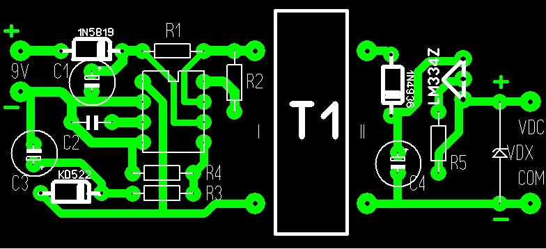
On the capacitor C4 is allocated about voltage 40V. Current stabilizer A2 and verifiable Zener diode VDX form parametric stabilizer, a multimeter, connected to the terminals X 1 and X 2 measures voltage on this stabilitrone.
При подключении анода к “+”, а катода к “-” диода или несимметричного стабилитрона мультиметр покажет очень малое напряжение. Если подключить в обратной полярности (как VDX на схеме), то для диода показания мультиметра будут около 40В, а для стабилитрона напряжение стабилизации (при условии, что оно ниже 40В).
It is clear that for symmetric concerning Zener voltage will be shown with any polarity connection.
Трансформатор Т1 намотан на ферритовом торообразном сердечнике внешним диаметром 23 мм. Обмотка 1 содержит 20 витков, а обмотка 2 содержит 35 витков провода ПЭВ 0,43. Важно, укладывать при намотке виток к витку. Причем, первичная обмотка намотана на одной части кольца, а вторичка – на другой. Не рекомендуется накладывать одну обмотку на другую.
When you configure, instead concerning VDX connect resistor 10 kohm R3 's resistance and ensure that the capacitor C4 established voltage 40V.
PCB: