Consider the push-pull bridge Converter, which in English-speaking countries called "bridge" (his concept is shown in Fig.1).
Fig. 1. Push-pull bridge Converter
Suppose the key to the gates of transistors VT2 and VT3 from the oscillator filed unlocking voltage. The current will flow through the circuit +Ewha woman, transistor VT3, transformer TV1, transistor VT2, Ewha woman. On the secondary side of the transformer TV1 will be an induced voltage, which straighten VD1 diode Assembly and smooth out the capacitor C1, and then a constant voltage is applied to the load. Thus, during the first stage transistors VT1 and VТ4 are in a state of cutoff, and transistors VT2 and VT3 blocking in the saturation state.
Will submit to the gates of transistors VT2 and VT3 blocking locking voltage, and the gates of the transistors VT1 and VТ4 – unlocking voltage. Chain +Ewha woman, transistor VT1, transformer TV1 , transistor VТ4, Ewha woman current to flow. On the secondary winding of the transformer TV1 is induced by the voltage that goes to the rectifier, performed on the diode Assembly VD1, filter capacitor C1, which will be supplied to the load.
During the second beat of the transistors VT2 and VT3 blocking were in a state of cutoff, and transistors VT1 and VТ4 in the saturation state. Through the load current flows in the first and second bars, whereby the frequency of the ripple voltage across the capacitor C1 is twice the frequency conversion. In the magnetic circuit of the transformer bridge Converter induction varies from a minimum value to a maximum value. With this private hysteresis loop is close to the limit hysteresis loop, and most completely, the magnetic properties of the transformer core.
The voltage across the primary winding of the pulse transformer bridge Converter can be found according to the expression:
![]()
where IP – DC voltage supply Converter;
InAs – the voltage drop on the key transistor in the saturation state.
Bridge converters are able to give to the load power up to tens of kilowatts, and in some cases even more.
Advantages:
- high efficiency;
- the ability to operate at very high power load;
- closed to the switching transistors is applied a reverse voltage equal to the DC voltage of the power Converter stage.
Bridge converters can be used in high-voltage power supply and allowed to turn without load, without resorting to any tricks. Output voltage ripple has a frequency that is twice the frequency conversion. Magnetization of the core of the pulse transformer bridge Converter arises when using non-identical transistors, the difference in the consumption of the load current during half cycles and many other reasons.
To reduce the effects of transient magnetization in transformer cores powerful bridge converters and half-bridge types, as well as converters with transformers with the midpoint of the primary winding, often impose non-magnetic gaps. This increases the triangular component of the primary current (the idle current), but allows you to load the SMPS for a dynamic load. In addition, to reduce bias in series with the pulse transformer of the bridge Converter includes a non-polar capacitor having a capacitance, the smallest value which can be found by the formula:
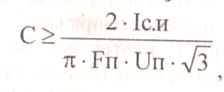
where IC.and pulse drain current of the transistor;
IP – ripple voltage on the capacitor;
Fп – frequency ripple.
For push-pull Converter (half-bridge, and a bridge Converter with a transformer having the midpoint of the primary winding) developed an effective electronic system for balancing magnetization reversal. Their relevance is shown at high power loads from a few kilowatts, the resistance of which varies widely (for example, arc welders).
K Disadvantages мостовых преобразователей относят наличие четырех ключевых транзисторов и, если отсутствует система защиты от перегрузки, – выход из строя компонентов ИИП при коротком замыкании нагрузки.